from IPython.display import Image
from IPython.core.display import HTML
Video discussion of content on this page
Some concepts
The only hardware that goes onto the FPGA is the hardware that you describe in your Verilog. This has a few implications . . .
- There are no init statements.
- If you initialize a register in Verilog, that register will obtain that value the first time the FPGA is programmed, but it will not retain that value through a reset.
- Instead, you must build a state machine with a reset state that initializes register values
- There are no system calls in Verilog.
- Because there's no system! The only hardware on the FPGA is that which you've described.
- You can't call
printbecause there's no printer (unless you build one) - You have to describe all the memory that you will use
- This makes debugging different. You will do most of your debugging in a simulation environment, and use LED's, HEX displays, switches, and an onboard logic analyzer to debug the FPGA
- There are no reals/floats.
- You have registers, which are just collections of bits
- You can make that register whatever size you want, but you just have collections of bits
- If you want to call that collection of bits an
intor afloat, then you have to write the routines that treat that collection of bits as that data type
- There is no timing information in Verilog. You do have a hardware clock.
- There's no concept of a
delay(ms)function call - If you want to delay for a certain amount of time, you must count off hardware clock cycles
- There's no concept of a
- Loops (in Verilog) are not sequential structures. They're repeated hardware.
- Sometimes that's what you want! But just remember that that's what these loops are doing.
- Modules are pieces of reusable hardware.
- Sort of looks and feels like a function (takes inputs, performs operations on those inputs, and returns outputs
- But! Everytime you instantiate a module, another copy of that hardware is placed on the FPGA
- Each "assign" and "always" happens all the time.
- If it can be happening, it is happening
- You can associate an always ith a logical condition (e.g. rising edge of a clock)
- There is no sequentiality except for that which you build!
- If you want sequential execution, build a state machine!
- An incomplete "case" or "if" can infer a latch.
- Inferred latches reviewed in a subsequent section
- Creates bugs that are hard to find
- Include a default case!
Recalling Inferred Latches
Consider the following code snippet:
always @ (*) begin
    case (sel)
        2'b_11: d=a ;
        2'b_10: d=b ;
        2'b_00: d=c ;
    endcase
end
What's the problem with the above Verilog? We forgot a case!! In the situation that sel assumes the value 2b_01, a latch will be inferred. The variable d will assume whatever it's most recently assigned value was, wihch could be nonsense. This is building a clockless flip-flop, and it will screw up your timing. In particular, this creates a set-reset flip-flop that is asynchronously set.
- This will not throw an error.
- Search your warnings for the keyword "inferred."
- And always include a default.
Blocking vs. Non-Blocking Assigns
Let me first introduce the rule of thumb, and then I'll motivate that rule of thumb.
The rule
If you are building combinatorial (unclocked) logic, use a blocking assign.
assign signal = x ;
Alternatively, if you are building sequential logic, use a non-blocking assign
signal <= x ;
Why is this the rule?
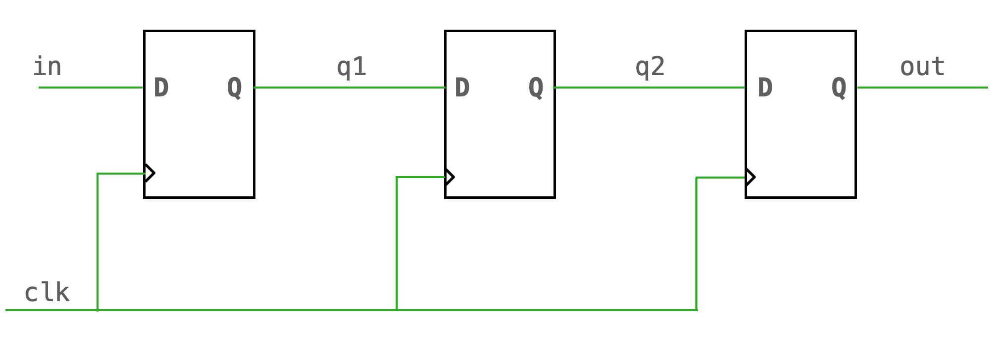
Let's consider two code snippets that are identical except that one uses a non-blocking assign and the other uses a blocking assign. We'll compare the hardware that each snippet builds. First, consider the non-blocking assign:
always @ (posedge clk) begin
    q1 <= in ;
    q2 <= q1 ;
    out <= q2 ;
end
The above Verilog builds the below hardware (a shift register!). Because we are using a non-blocking assign, the right side of each of the above expressions is simultaneously moved to the left side of each of the above expressions.
Now consider the case that we used blocking assigns, as shown below:
always @ (posedge clk) begin
    q1 = in ;
    q2 = q1 ;
    out = q2 ;
end
This builds a different circuit. The compiler will look at this and build a circuit for which q1 assumes the value of in, and then q2 assumes the value of q1, and then out assumes the value of q2. It does not execute these sequentially, everything is executed simultaneously, but it will build a circuit that satisfies this logic. That circuit looks like this:
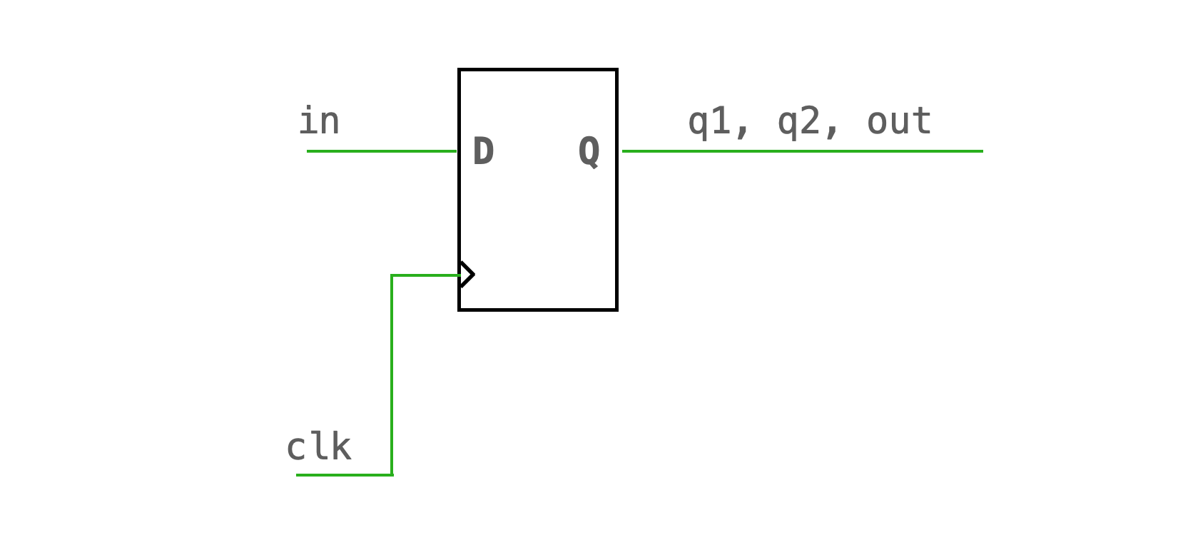
At the rising edge of the clock, q1, q2, and out all get the value of in. For a shift register, that's not what we want. But! For combinatorial logic that is what we want! Consider instead this snippet:
always @ (a or b or c) begin
    x = a & b ;
    y = x | c ;
end
The above Verilog builds the below circuit:
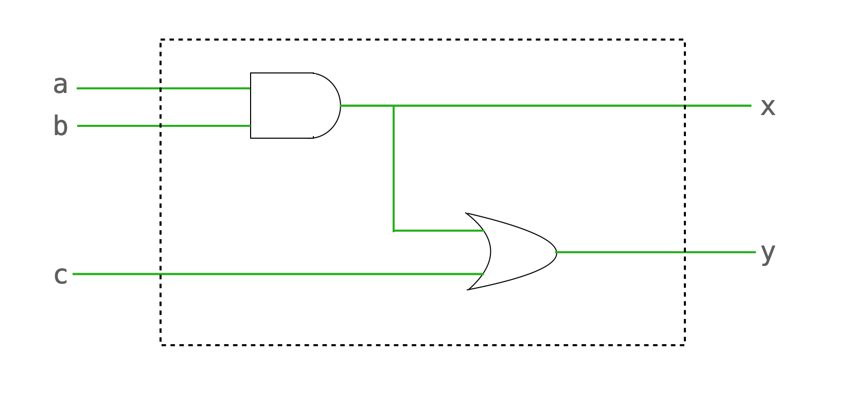
The circuit AND's a and b, OR's that with c, and puts that in some register y.
Note: If you assign a signal in one always block, you cannot assign it anywhere else. (Be careful, the simulation environment will let you do this!)
Multiplexing in Verilog
Suppose that we want to build a 2:1 mux like the one shown below:
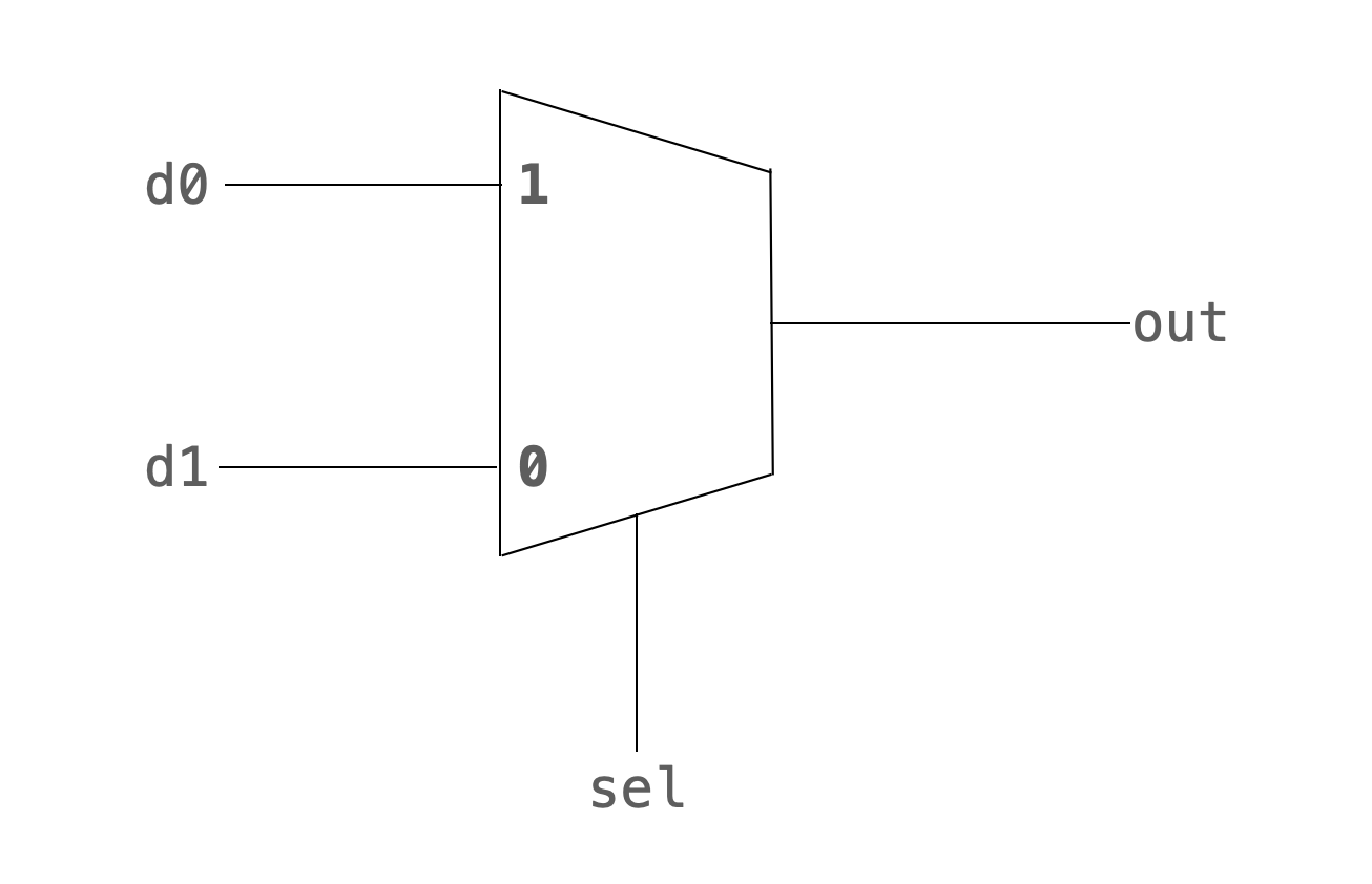
There are (at least) three ways to do this:
Conditional assigns
I find this particular syntax for multiplexing very nice for doing state transitions in state machines. However, for anything larger than two conditions, this becomes cumbersome and error prone.
assign out = (sel)? d1:d0 ;
If statements
always @ (*) begin
    if (sel == 1'b_0) begin
        out = d1 ;
    end
    else begin
        out = d0 ;
    end
end
Case statements
If I had more than two possible conditions, I'd include a default!
always @ (*) begin
    case (sel)
        1'b_0: out = d1 ;
        1'b_1: out = d0 ;
    endcase
end
A couple more things to be careful about
- Be careful to declare signed registers as such. Otherwise they default to unsigned.
reg signed [31:0] x ;
Be careful when shifting signed registers
- Signed shift: "<<<", ">>>"
- Unsigned shift: ">>", "<<"
Search your warnings for the keyword "implicit."
- Lets you know your using a register that you haven't initialized
- This doesn't throw an error! It will create a register that is 1-bit wide and create hard-to-track-down bugs
Be obsessive about register sizes!