The VGA Standard
The VGA standard is described on a webpage for a different project. That content is copied below so that this webpage can stand alone.
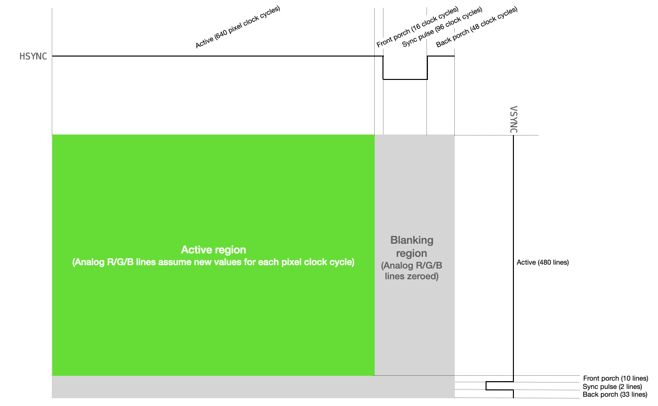
Driving a VGA screen requires manipulating two digital synchronization pins and three analog color pins (RED, GREEN, and BLUE). One of the synchronization pins, HSYNC, tells the screen when to move to a new row of pixels. The other synchronization pin, VSYNC, tells the screen when to start a new frame. The protocol is described below, both textually and visually.
- The VGA pixel clock runs at 25.172 MHz (on my VGA screen, I can get away with 25 MHz)
- Both
HSYNCandVSYNCstart in active mode (logic level high) HSYNCremains in active mode for 640 pixel clock cycles (i.e., one row of the VGA display).- For each of the 640 clock cycles, the voltages on the
RED,GREEN, andBLUElines are varied between 0 and 0.7V, with each voltage representing the intensity of that particular color for a particular pixel. - After 640 clock cycles, the
RED,GREEN, andBLUElines are set to 0, and theHSYNCline remains high thru its frontporch (16 pixel clock cycles). HSYNCis set to logic-level low for 96 pixel clock cycles (this is the horizontal sync pulse)HSYNCis set to logic-level high thru its backporch (48 pixel clock cycles).HSYNCthen returns to the start of active mode (step 2, above), and the process is repeated for the next row of pixels. Each row of pixels is a line.VSYNCremains in active mode (logic level high) for 480 lines.- After 480 lines, the voltages on the
RED,GREEN, andBLUElines are set to 0, and theVSYNCline remains high thru its frontporch (10 lines). VSYNCis set to logic-level low for 2 lines (this is the vertical sync pulse).VSYNCis set to logic-level high thru its backporch (33 lines).VSYNCthen returns to the start of active mode (step 2, above), and the process is repeated for the next frame.
Verilog VGA Driver
The VGA driver provided below could be written more efficiently. In particular, some of the horizontal and vertical states in the state machine could be consolidated. I left these states separate so that the below Verilog maps as clearly as possible to the timing diagrams described in the previous section.
I chose 8-bit (RRRGGGBB) color because of M10K memory limitations on the DE1-SoC.
module vga_driver (
    input wire clock,     // 25 MHz
    input wire reset,     // Active high
    input [7:0] color_in, // Pixel color data (RRRGGGBB)
    output [9:0] next_x,  // x-coordinate of NEXT pixel that will be drawn
    output [9:0] next_y,  // y-coordinate of NEXT pixel that will be drawn
    output wire hsync,    // HSYNC (to VGA connector)
    output wire vsync,    // VSYNC (to VGA connctor)
    output [7:0] red,     // RED (to resistor DAC VGA connector)
    output [7:0] green,   // GREEN (to resistor DAC to VGA connector)
    output [7:0] blue,    // BLUE (to resistor DAC to VGA connector)
    output sync,          // SYNC to VGA connector
    output clk,           // CLK to VGA connector
    output blank          // BLANK to VGA connector
);

    // Horizontal parameters (measured in clock cycles)
    parameter [9:0] H_ACTIVE  =  10'd_639 ;
    parameter [9:0] H_FRONT   =  10'd_15 ;
    parameter [9:0] H_PULSE   =  10'd_95 ;
    parameter [9:0] H_BACK    =  10'd_47 ;

    // Vertical parameters (measured in lines)
    parameter [9:0] V_ACTIVE   =  10'd_479 ;
    parameter [9:0] V_FRONT    =  10'd_9 ;
    parameter [9:0] V_PULSE =  10'd_1 ;
    parameter [9:0] V_BACK  =  10'd_32 ;

    // Parameters for readability
    parameter   LOW     = 1'b_0 ;
    parameter   HIGH    = 1'b_1 ;

    // States (more readable)
    parameter   [7:0]    H_ACTIVE_STATE    = 8'd_0 ;
    parameter   [7:0]   H_FRONT_STATE     = 8'd_1 ;
    parameter   [7:0]   H_PULSE_STATE   = 8'd_2 ;
    parameter   [7:0]   H_BACK_STATE     = 8'd_3 ;

    parameter   [7:0]    V_ACTIVE_STATE    = 8'd_0 ;
    parameter   [7:0]   V_FRONT_STATE    = 8'd_1 ;
    parameter   [7:0]   V_PULSE_STATE   = 8'd_2 ;
    parameter   [7:0]   V_BACK_STATE     = 8'd_3 ;

    // Clocked registers
    reg              hysnc_reg ;
    reg              vsync_reg ;
    reg     [7:0]   red_reg ;
    reg     [7:0]   green_reg ;
    reg     [7:0]   blue_reg ;
    reg              line_done ;

    // Control registers
    reg     [9:0]   h_counter ;
    reg     [9:0]   v_counter ;

    reg     [7:0]    h_state ;
    reg     [7:0]    v_state ;

    // State machine
    always@(posedge clock) begin
        // At reset . . .
        if (reset) begin
            // Zero the counters
            h_counter   <= 10'd_0 ;
            v_counter   <= 10'd_0 ;
            // States to ACTIVE
            h_state     <= H_ACTIVE_STATE  ;
            v_state     <= V_ACTIVE_STATE  ;
            // Deassert line done
            line_done   <= LOW ;
        end
        else begin
            //////////////////////////////////////////////////////////////////////////
            ///////////////////////// HORIZONTAL /////////////////////////////////////
            //////////////////////////////////////////////////////////////////////////
            if (h_state == H_ACTIVE_STATE) begin
                // Iterate horizontal counter, zero at end of ACTIVE mode
                h_counter <= (h_counter==H_ACTIVE)?10'd_0:(h_counter + 10'd_1) ;
                // Set hsync
                hysnc_reg <= HIGH ;
                // Deassert line done
                line_done <= LOW ;
                // State transition
                h_state <= (h_counter == H_ACTIVE)?H_FRONT_STATE:H_ACTIVE_STATE ;
            end
            if (h_state == H_FRONT_STATE) begin
                // Iterate horizontal counter, zero at end of H_FRONT mode
                h_counter <= (h_counter==H_FRONT)?10'd_0:(h_counter + 10'd_1) ;
                // Set hsync
                hysnc_reg <= HIGH ;
                // State transition
                h_state <= (h_counter == H_FRONT)?H_PULSE_STATE:H_FRONT_STATE ;
            end
            if (h_state == H_PULSE_STATE) begin
                // Iterate horizontal counter, zero at end of H_PULSE mode
                h_counter <= (h_counter==H_PULSE)?10'd_0:(h_counter + 10'd_1) ;
                // Clear hsync
                hysnc_reg <= LOW ;
                // State transition
                h_state <= (h_counter == H_PULSE)?H_BACK_STATE:H_PULSE_STATE ;
            end
            if (h_state == H_BACK_STATE) begin
                // Iterate horizontal counter, zero at end of H_BACK mode
                h_counter <= (h_counter==H_BACK)?10'd_0:(h_counter + 10'd_1) ;
                // Set hsync
                hysnc_reg <= HIGH ;
                // State transition
                h_state <= (h_counter == H_BACK)?H_ACTIVE_STATE:H_BACK_STATE ;
                // Signal line complete at state transition (offset by 1 for synchronous state transition)
                line_done <= (h_counter == (H_BACK-1))?HIGH:LOW ;
            end
            //////////////////////////////////////////////////////////////////////////
            ///////////////////////// VERTICAL ///////////////////////////////////////
            //////////////////////////////////////////////////////////////////////////
            if (v_state == V_ACTIVE_STATE) begin
                // increment vertical counter at end of line, zero on state transition
                v_counter<=(line_done==HIGH)?((v_counter==V_ACTIVE)?10'd_0:(v_counter+10'd_1)):v_counter ;
                // set vsync in active mode
                vsync_reg <= HIGH ;
                // state transition - only on end of lines
                v_state<=(line_done==HIGH)?((v_counter==V_ACTIVE)?V_FRONT_STATE:V_ACTIVE_STATE):V_ACTIVE_STATE ;
            end
            if (v_state == V_FRONT_STATE) begin
                // increment vertical counter at end of line, zero on state transition
                v_counter<=(line_done==HIGH)?((v_counter==V_FRONT)?10'd_0:(v_counter + 10'd_1)):v_counter ;
                // set vsync in front porch
                vsync_reg <= HIGH ;
                // state transition
                v_state<=(line_done==HIGH)?((v_counter==V_FRONT)?V_PULSE_STATE:V_FRONT_STATE):V_FRONT_STATE;
            end
            if (v_state == V_PULSE_STATE) begin
                // increment vertical counter at end of line, zero on state transition
                v_counter<=(line_done==HIGH)?((v_counter==V_PULSE)?10'd_0:(v_counter + 10'd_1)):v_counter ;
                // clear vsync in pulse
                vsync_reg <= LOW ;
                // state transition
                v_state<=(line_done==HIGH)?((v_counter==V_PULSE)?V_BACK_STATE:V_PULSE_STATE):V_PULSE_STATE;
            end
            if (v_state == V_BACK_STATE) begin
                // increment vertical counter at end of line, zero on state transition
                v_counter<=(line_done==HIGH)?((v_counter==V_BACK)?10'd_0:(v_counter + 10'd_1)):v_counter ;
                // set vsync in back porch
                vsync_reg <= HIGH ;
                // state transition
                v_state<=(line_done==HIGH)?((v_counter==V_BACK)?V_ACTIVE_STATE:V_BACK_STATE):V_BACK_STATE ;
            end

            //////////////////////////////////////////////////////////////////////////
            //////////////////////////////// COLOR OUT ///////////////////////////////
            //////////////////////////////////////////////////////////////////////////
            // Assign colors if in active mode
            red_reg<=(h_state==H_ACTIVE_STATE)?((v_state==V_ACTIVE_STATE)?{color_in[7:5],5'd_0}:8'd_0):8'd_0 ;
            green_reg<=(h_state==H_ACTIVE_STATE)?((v_state==V_ACTIVE_STATE)?{color_in[4:2],5'd_0}:8'd_0):8'd_0 ;
            blue_reg<=(h_state==H_ACTIVE_STATE)?((v_state==V_ACTIVE_STATE)?{color_in[1:0],6'd_0}:8'd_0):8'd_0 ;

        end
    end
    // Assign output values - to VGA connector
    assign hsync = hysnc_reg ;
    assign vsync = vsync_reg ;
    assign red = red_reg ;
    assign green = green_reg ;
    assign blue = blue_reg ;
    assign clk = clock ;
    assign sync = 1'b_0 ;
    assign blank = hysnc_reg & vsync_reg ;
    // The x/y coordinates that should be available on the NEXT cycle
    assign next_x = (h_state==H_ACTIVE_STATE)?h_counter:10'd_0 ;
    assign next_y = (v_state==V_ACTIVE_STATE)?v_counter:10'd_0 ;

endmodule
Instantiating and using the driver on the DE1-SoC
On the DE1-SoC, this module can be used in the following way:
- Create a 25 MHz Phase-Locked-Loop, and attach that to the
clockinput of the module. - Attach the
resetinput to a register in the module which instantiates the vga driver. Pulse this input high to instantiate the control registers in the driver, then keep it low. - At every rising edge of the 25 MHz clock, the vga driver will indicate the x and y coordinates for the next pixel that it will draw on the
next_xandnext_youtputs from the module. - By the next rising edge, the instantiating module must calculate or lookup the color for that pixel (8-bit, RRRGGGBB) and put that color on the
color_ininput to the module.- NOTE: If you are storing pixel color data in M10k memory, remember that there is a 1-cycle delay associated with memory reads. Thus, the clock for the memory must be running at at least 75 MHz.
- All of the other module outputs (
VGA_HS,VGA_VS,VGA_R,VGA_G,VGA_B,VGA_SYNC_N,VGA_CLK, andVGA_BLANK_N) are connected directly to the VGA i/o in the Computer_system module.
Example
Here is an example of an instantiation:
// Instantiate VGA driver
vga_driver draw   ( .clock(vga_pll),        // 25 MHz PLL
                    .reset(vga_reset),      // Active high reset, manipulated by instantiating module
                    .color_in(pixel_color), // Pixel color (RRRGGGBB) for pixel being drawn
                    .next_x(next_x),        // X-coordinate (range [0, 639]) of next pixel to be drawn
                    .next_y(next_y),        // Y-coordinate (range [0, 479]) of next pixel to be drawn
                    .hsync(VGA_HS),         // All of the connections to the VGA screen below
                    .vsync(VGA_VS),
                    .red(VGA_R),
                    .green(VGA_G),
                    .blue(VGA_B),
                    .sync(VGA_SYNC_N),
                    .clk(VGA_CLK),
                    .blank(VGA_BLANK_N)
);
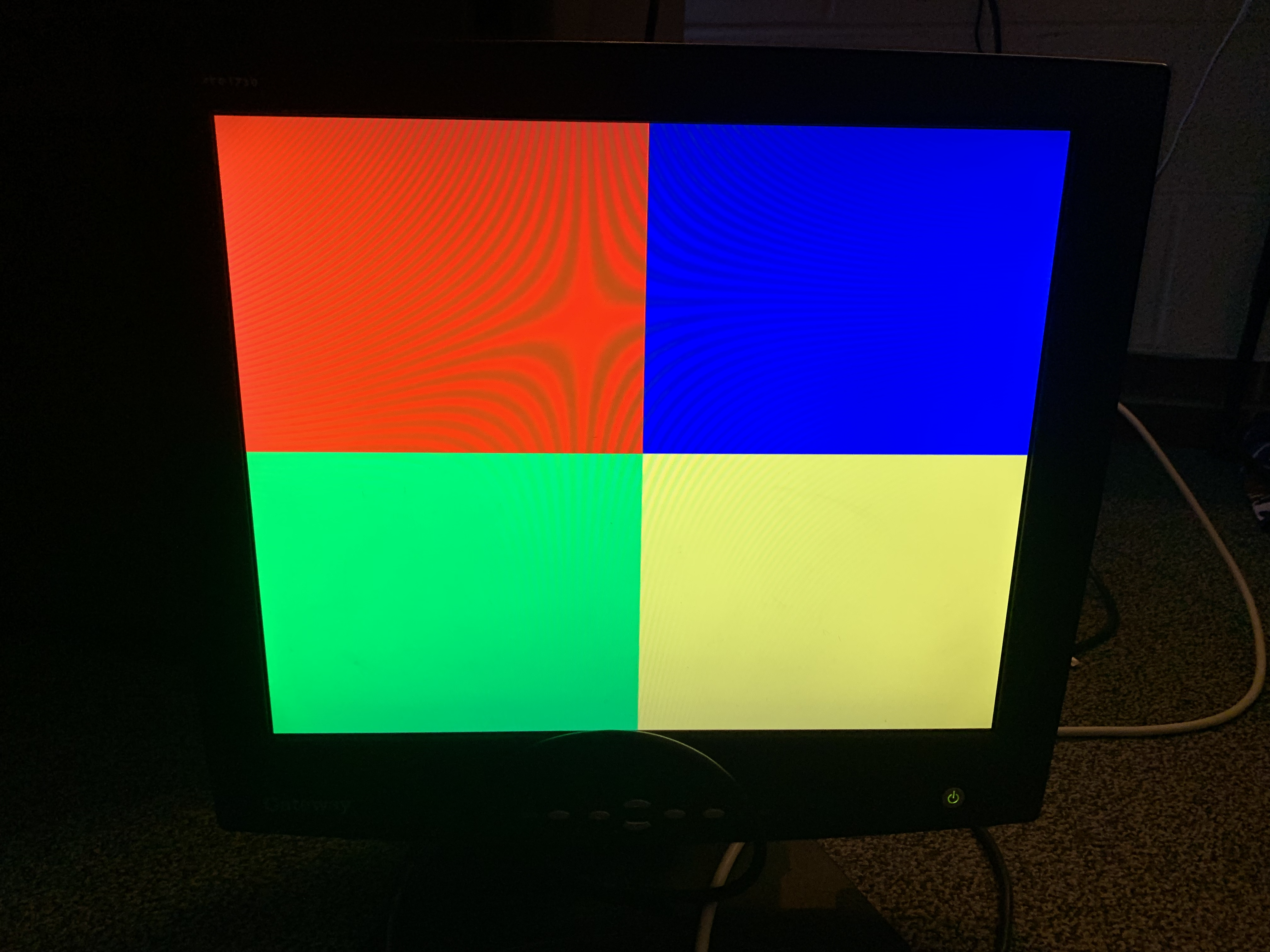
This project demonstrates the driver. The module which instantiates the driver writes a simple checkerboard pattern (pictured below) to M10K memory. The module uses the next_x and next_y outputs from the vga driver to set the read address for the memory and access pixel color information. Artifacts are from the camera and are not visible on the VGA.
The Mandelbrot renderer demonstrated below also uses this driver: