AM Radio Transmitter Implemented with PWM on Raspberry Pi Pico
V. Hunter Adams
Description and demonstration video
An AM radio operates by modulating the amplitude of a carrier wave with a lower-frequency message-carrying wave. Often, that message-carrying wave is an audio waveform. In this project, the carrier wave is approximated by a PWM signal generated by the RP2040, and the audio waveform modulates its average amplitude by modifying its duty cycle. Over short ranges, the fields generated by these PWM waves in a short jumper cable can be picked up and demodulated by an AM radio, as shown below.
Overview of code
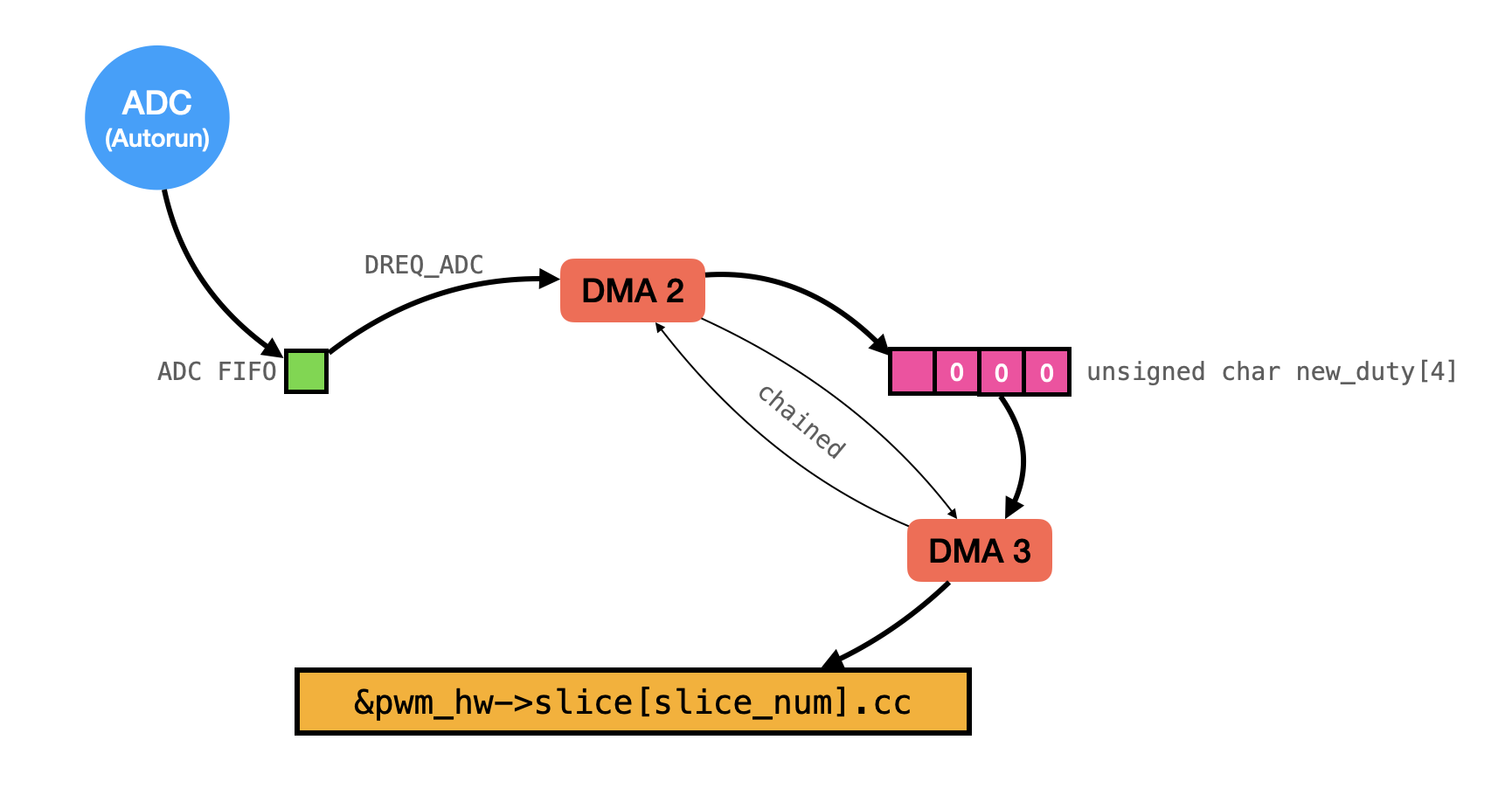
This application uses zero CPU-time, making use exclusively of peripherals. The ADC is configured to free-running mode, and gathers new samples at 10kHz. Each of these samples is truncated to 8 bits, and put into the ADC FIFO. A DMA channel, paced by DREQ_ADC, moves each of these samples as it appears from the FIFO to the first index of a 4-element character array (all other elements zero). This DMA channel chains to a second DMA channel, which moves the character array to the counter compare register for the PWM channel.
The PWM channel is configured with a clock divider of 1, and a wrapval of 255. The RP2040 is overclocked to 250MHz, so the frequency of the square wave is ~980kHz. When the DMA channel moves an 8-bit (0-255) value from the ADC FIFO to the counter compare register, the duty cycle for the square wave will be adjusted on the next rising edge. A wrapval of 255 was chosen so that the ADC samples could set the duty cycle directly.
This second DMA channel then chains back to the first, which waits for a new sample to appear in the ADC FIFO.
Stepping thru the code
A listing of all of the code is provided at the bottom of this webpage, and available in this repository. This section provides a brief commentary on each section.
Includes, macros, and global variables
The project includes three standard C libraries, two high-level SDK libraries, and three hardware interface libraries. In particular, it includes the interface libraries to the PWM peripheral, the ADC, and the DMA. Macros are used to associate names with parameter values, and a couple of global variables are declared. slice_num is an unsigned int which will store the slice number for the PWM channel that we are using, and new_duty is a character array into which one DMA channel will place ADC samples, and from which a second DMA channel will move data to the counter compare register.
Why is new_duty a four-element character array? I was experimenting with the consequences of having a mismatch between DMA transfer data size and destination data size. In order to perform DMA transfers out of the ADC FIFO, the channel must be configured for a transfer data size of 8 bits. Experimentation shows that pointing this DMA channel to a 32-bit wide unsigned int works (the data ends up in the bottom 8 bits of that variable). But! If one specifies the destination address to be a register, then those 8 bits are copied four times into the 32-bit register. I deduced this by printing the value contained at a register (in particular, the CC register for PWM slice 2) before and after a DMA transaction. Alternatively, a 32-bit transaction from an 8-bit source put some garbage data (from adjacent memory?) into the register. Experimentation showed that a 32-bit transaction from a character array worked. An 8-bit DMA transfer from the ADC FIFO to an unsigned int, then a 32-bit transaction from the unsigned int to the register, would also work.
Main
System configuration and initialization
The first line in main overclocks the system PLL to 250 MHz. This is because I knew that I wanted for the PWM wrapval to be 255, so I needed for the system clock to be fast enough for a PWM channel with a 255 wrapval to still be in the AM radio frequency range. The default clock rate of 125MHz would have made the PWM frequency ~490kHz, which is a little low.
PWM configuration
The PWM channel is configured with a wrapval of 255 (so that it can be set directly from the ADC samples) and a clock divider of 1 (so that it runs as fast as possible). I experimented a bit with modifying the drive strength and slew rate of the GPIO toggled by the PWM peripheral, to no discernable effect. I thought perhaps that modifying the slew rate would be a mechanism by which I could implement FM transmissions on one of the higher-frequency harmonics of the square wave. Doesn't seem to work for that though.
ADC configuration
The ADC is configured per datasheet specifications for interaction with a DMA channel. In particular, it is configured to write gathered samples to the FIFO, enable the DMA DREQ when any sample appears in the FIFO, disable the error bit, and truncate to 8 bit samples. The ADC clock is configured to overflow at 10 MHz, but the ADC is not started until after the DMA channels are configured and started. Order for these operations matters!
DMA configuration
Two DMA channels are configured, each of which chains to the other. The first DMA channel moves data from the ADC FIFO to the first element of the new_duty character array. This channel is paced by DREQ_ADC, so that a transaction occurs each time a new sample appears in the FIFO. After each transaction, the second DMA channel is triggered to move the ADC data from the character array to the counter compare register for the PWM channel, and then restart the first channel to wait for the next sample. As such, the duty cycle for the PWM wave adjusts automatically each time the ADC generates a sample.
Code listings
Source file
/**
 * V. Hunter Adams (vha3@cornell.edu)
 *
 * AM Radio transmission with PWM
 *
 * This demonstration uses a PWM channel
 * to generate an AM radio transmission modulated
 * by an ADC input (probably a mic or aux cable).
 *
 * HARDWARE CONNECTIONS
 *   - GPIO 4 ---> PWM output
 *   - GPIO 25 --> ADC input
 *
 * RESOURCES CONSUMED
 *   - ADC
 *   - 2 DMA channels
 *   - 1 PWM channel
 *
 */

////////////////////////////////////////////////////////////////////////
///////////////////////// INCLUDES /////////////////////////////////////
////////////////////////////////////////////////////////////////////////
// standard libraries
#include <stdio.h>
#include <stdlib.h>
#include <string.h>

// high-level libraries
#include "pico/stdlib.h"
#include "pico/multicore.h"

// hardware-interface libraries
#include "hardware/pwm.h"
#include "hardware/dma.h"
#include "hardware/adc.h"

////////////////////////////////////////////////////////////////////////
///////////////////////// MACROS ///////////////////////////////////////
////////////////////////////////////////////////////////////////////////
// PWM wrap value and clock divide value
// For a CPU rate of 250 MHz, this gives
// a PWM frequency of ~980kHz
#define WRAPVAL 255
#define CLKDIV 1.0f

// ADC Mux input 0, on GPIO 26
// Sample rate of 10KHz, ADC clock rate of 48MHz
#define ADC_CHAN 0
#define ADC_PIN 26
#define Fs 10000.0
#define ADCCLK 48000000.0

// PWM pin
#define PWM_PIN 4

////////////////////////////////////////////////////////////////////////
///////////////////////// GLOBALS //////////////////////////////////////
////////////////////////////////////////////////////////////////////////
// Variable to hold PWM slice number
uint slice_num ;

// Array for shuffling ADC sample
unsigned char new_duty[4] = {64, 0, 0, 0} ;

int main() {

    ////////////////////////////////////////////////////////////////////////
    ////////////// SYSTEM CONFIGURATION AND INTIALIZATION //////////////////
    ////////////////////////////////////////////////////////////////////////
    // Overclock to 250MHz
    set_sys_clock_khz(250000, true);

    // Initialize stdio
    stdio_init_all();

    ////////////////////////////////////////////////////////////////////////
    ///////////////////////// PWM CONFIGURATION ////////////////////////////
    ////////////////////////////////////////////////////////////////////////
    // Tell GPIO 4 that it is allocated to the PWM, max slew rate and
    // drive strength
    gpio_set_function(PWM_PIN, GPIO_FUNC_PWM);
    gpio_set_drive_strength(PWM_PIN, 3);
    gpio_set_slew_rate(PWM_PIN, 1);

    // Find out which PWM slice is connected to GPIO 4 (it's slice 2)
    slice_num = pwm_gpio_to_slice_num(PWM_PIN);

    // This section configures the period of the PWM signals
    pwm_set_wrap(slice_num, WRAPVAL) ;
    pwm_set_clkdiv(slice_num, CLKDIV) ;

    // This sets duty cycle. Will be modified by the DMA channel
    pwm_set_chan_level(slice_num, PWM_CHAN_A, 128);

    // Start the channel
    pwm_set_mask_enabled((1u << slice_num));

    ///////////////////////////////////////////////////////////////////
    // ==================== ADC CONFIGURATION =========================
    ///////////////////////////////////////////////////////////////////
    // Init GPIO for analogue use: hi-Z, no pulls, disable
    // digital input buffer.
    adc_gpio_init(ADC_PIN);

    // Initialize the ADC harware
    // (resets it, enables the clock, spins until the hardware is ready)
    adc_init() ;

    // Select analog mux input (0...3 are GPIO 26, 27, 28, 29; 4 is temp sensor)
    adc_select_input(ADC_CHAN) ;

    // Setup the FIFO
    adc_fifo_setup(
        true,    // Write each completed conversion to the sample FIFO
        true,    // Enable DMA data request (DREQ)
        1,       // DREQ (and IRQ) asserted when at least 1 sample present
        false,   // We won't see the ERR bit because of 8 bit reads; disable.
        true     // Shift each sample to 8 bits when pushing to FIFO
    );

    // Divisor of 0 -> full speed. Free-running capture with the divider is
    // equivalent to pressing the ADC_CS_START_ONCE button once per `div + 1`
    // cycles (div not necessarily an integer). Each conversion takes 96
    // cycles, so in general you want a divider of 0 (hold down the button
    // continuously) or > 95 (take samples less frequently than 96 cycle
    // intervals). This is all timed by the 48 MHz ADC clock. This is setup
    // to grab a sample at 10kHz (48Mhz/10kHz - 1)
    adc_set_clkdiv(ADCCLK/Fs);

    ///////////////////////////////////////////////////////////////////////
    // ============================== DMA CONFIGURATION ===================
    ///////////////////////////////////////////////////////////////////////

    // DMA channels for sampling ADC. Using 2 and 3 in case I want to add
    // the VGA driver to this project
    int sample_chan = 2 ;
    int control_chan = 3 ;

    // Channel configurations (start with the default)
    dma_channel_config c2 = dma_channel_get_default_config(sample_chan);
    dma_channel_config c3 = dma_channel_get_default_config(control_chan);

    // Setup the ADC sample channel
    // Reading from constant address, in 8-bit chunks, writing to constant address
    channel_config_set_transfer_data_size(&c2, DMA_SIZE_8);
    channel_config_set_read_increment(&c2, false);
    channel_config_set_write_increment(&c2, false);
    // Pace transfers based on availability of ADC samples
    channel_config_set_dreq(&c2, DREQ_ADC);
    // Chain to control channel
    channel_config_set_chain_to(&c2, control_chan);
    // Configure the channel
    dma_channel_configure(
        sample_chan,        // channel to be configured
        &c2,                // channel config
        &new_duty[0],       // dst
        &adc_hw->fifo,      // src
        1,                  // transfer count
        false               // don't start immediately
    );

    // Setup the control channel
    // 32-bit txfers, no read or write incrementing, chain to sample chan
    channel_config_set_transfer_data_size(&c3, DMA_SIZE_32);
    channel_config_set_read_increment(&c3, false);
    channel_config_set_write_increment(&c3, false);
    channel_config_set_chain_to(&c3, sample_chan);

    dma_channel_configure(
        control_chan,                  // channel to be configured
        &c3,                           // The configuration we just created
        &pwm_hw->slice[slice_num].cc,  // dst (PWM counter compare reg)
        &new_duty[0],                  // src (where the other DMA put the data)
        1,                             // transfer count
        false                          // don't start immediately
    );

    // Start the DMA channel (before the ADC!)
    dma_start_channel_mask(1u << sample_chan) ;

    // Start the ADC
    adc_run(true) ;

    // Exit main :)

}
CMakeLists.txt
add_executable(am_demo)

# must match with executable name and source file names
target_sources(am_demo PRIVATE am-demo.c)

# Add pico_multicore which is required for multicore functionality
target_link_libraries(am_demo pico_stdlib pico_multicore hardware_pwm hardware_dma hardware_adc)

# create map/bin/hex file etc.
pico_add_extra_outputs(am_demo)
AM Radio Beacon
We can generate pure tones by simply turning the PWM channel on and off (rather than modulating its duty cycle with an audio waveform). The simplified code available here generates a 1KHz tone at ~41.6 MHz for one second, then generates just the carrier wave for 1 second. The video below shows an FFT/waterfall plot of these transmissions.