CAN 2.0 driver using PIO coprocessors on the RP2040
V. Hunter Adams - Go back to homepage
Summary, demonstration, and link to code
This project implements the CAN 2.0 protocol using the PIO coprocessors on the RP2040. Features and specifications include:
- The CAN transmitter and receiver are implemented on separate ARM cores, separate PIO blocks, and utilize separate DMA channels. As such, they are wholly independent. The execution of one has no effect on the execution of the other.
- The CAN transmitter supports arbitrary and variable payload lengths.
- The CAN transmitter supports user-specified and run-time-modifiable idle-time between packets.
- The CAN transmitter performs bus idle checks before transmission, and performs priority arbitration among nodes.
- The CAN receiver re-synchronizes on every change of polarity in a received bitstring.
- Each packet contains a checksum for error catching.
- Each packet contains a flexible reserve bit for future utilization (routing? data requests?).
- All aspects of the physical and packet layer are easily modifiable. (E.g. baud rate, packet rate, and packet structure).
- Program code consumes ~27kB of flash memory
- There is no measurable bit error rate with present configurations.
- A test infrastructure is built to study bit error rate changes with changes to the physical layout of the bus. If errors manifest under different conditions (e.g. extremely long bus cables), then mitigating action can be taken (e.g. decreasing baud rate, or increasing idle time between packets).
A video demonstration of the driver is embedded below.
System overview
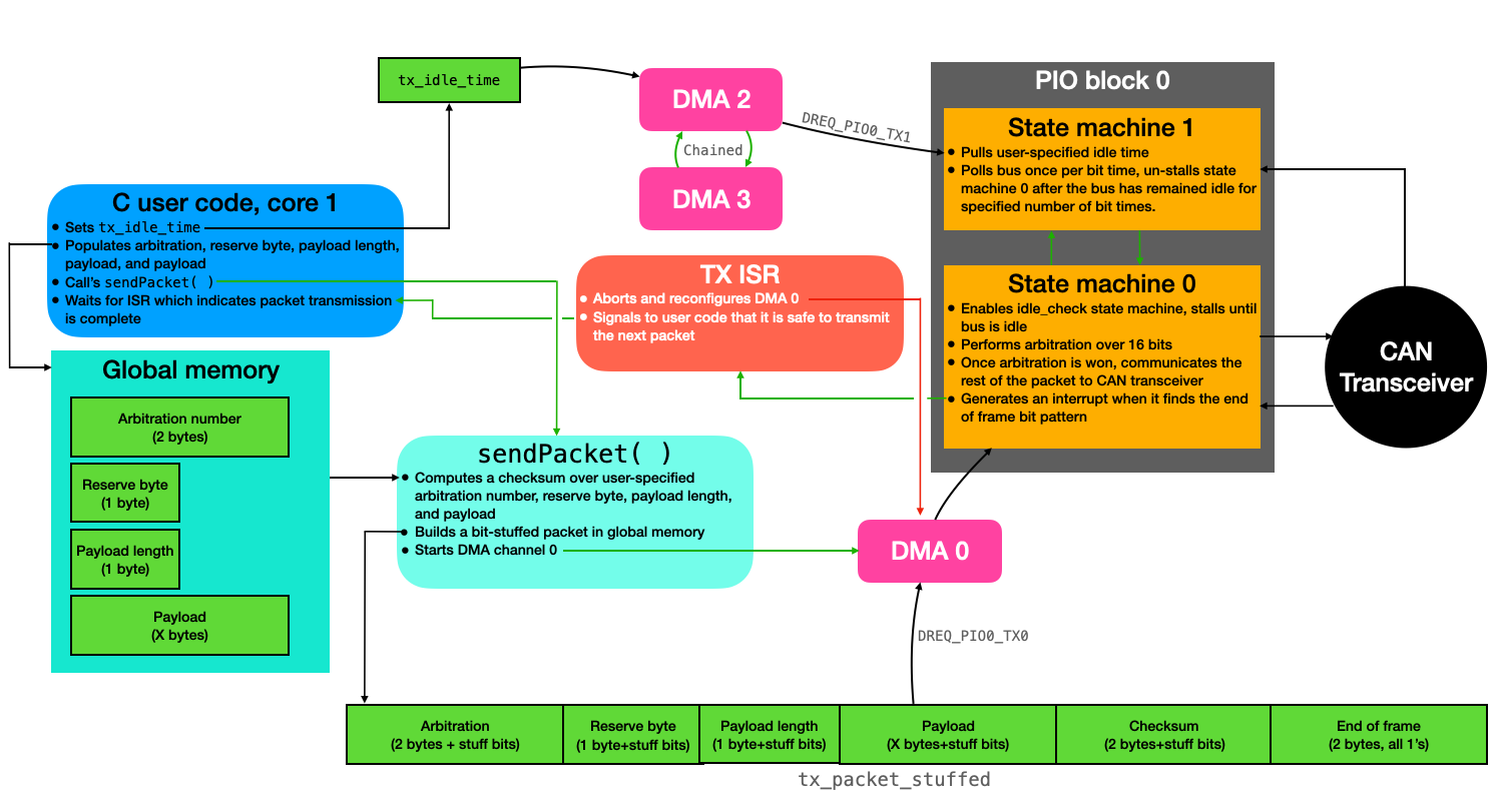
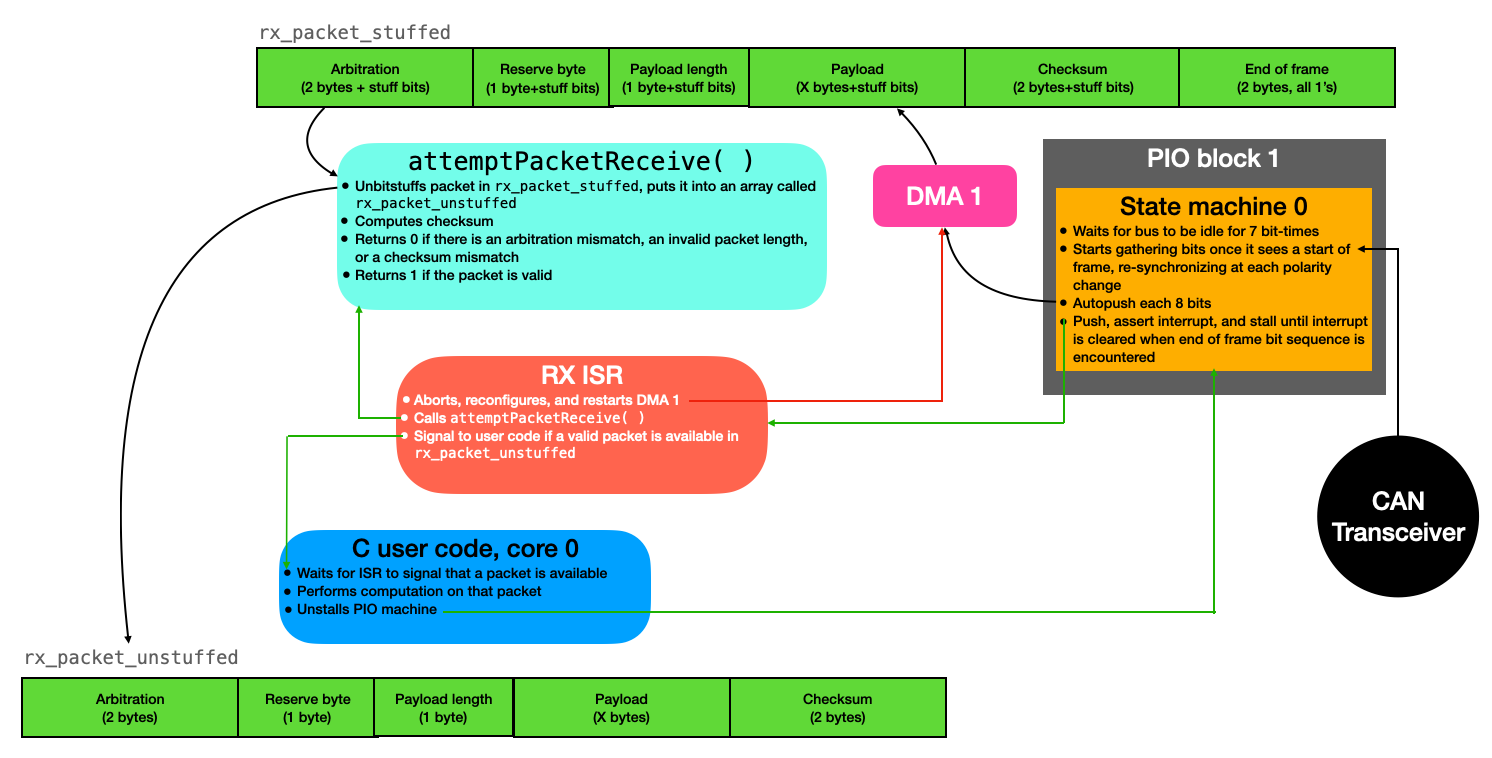
The diagrams below provide a high-level overview of the transmitter/receiver architecture. Each lives on separate cores and separate co-processors, so that there is no interaction whatsoever between them. In each of the diagrams, green arrows can be read as "triggers," red arrows can be red as "terminates," and black arrows indicate the flow of data.
In anticipation of the addition of sensors and other peripherals, user code is currently arranged using the threading library ProtoThreads. This makes user code highly modular and easy to augment.
Transmitter
User code specifies packet information (arbitration ID, reserve byte value, payload length, and payload), and then calls a function called sendPacket(). This function computes a checksum over the user-specified data, and populates a complete packet (bit stuffing as it does so). Once the packet is assembled, this function then starts DMA channel 0, which shuffles the packet (16 bits at a time) over to the PIO state machine. This state machine is described in detail in a later section but, in short, it makes sure that the bus is idle, performs arbitration, and then communicates the payload. The PIO state machine sends an interrupt back to the CPU to indicate that it has finished with transmission and is ready for the next packet. In the meantime, user code may be calculating the next packet to send.
Receiver
The receiving PIO program sits and waits for a start bit. When it sees one, it samples the bus once per bit time (re-synchronizing at each change in polarity). These data are autopushed 8 bits at a time to the array rx_packet_stuffed. When the PIO state machine encounters the end of frame bit sequence, it throws an interrupt to the CPU and stalls until the CPU clears that interrupt. The CPU enters an interrupt service routine, aborts the DMA channel which moves data from the PIO machine to the buffer, and calls the function attemptPacketReceive( ). This function un-bitstuffs the received packet into rx_packet_unstuffed, and computes a checksum over the data that it finds. The function will return 0 if it finds an arbitration identification mismatch, a checksum mismatch, or an out-of-bounds payload length. Otherwise, it will return a 1 to indicate a valid packet. The ISR may then perform some computation or routing on that received data, or signal a user thread to run. It then resets the write address for the DMA channel, restarts it, and clears the PIO interrupt to un-stall the state machine.
API and programmer's model
Application program structure
Please find an example program at this link. This example follows the general structure for a user program that uses this driver, which is:
- Includes for necessary libraries
- Declaration of user global variables
- Definition of transmit complete ISR
- Calls
resetTransmitter() - Signals to a thread that it is safe to transmit again
- Calls
- Definition of packet receive ISR
- Calls
resetReceiver() - Calls
attemptPacketReceive() - Does whatever user wants with received packet
- Calls
acceptNewPacket()to un-stall PIO machine
- Calls
- Definition of user threads
- Probably one which sets payload data, waits for signal from tx isr, then calls
sendPacket() - Probably another which pets a watchdog timer
- Any others that are required for a particular application (reading sensors? routing?)
- Probably one which sets payload data, waits for signal from tx isr, then calls
main()for core 1- Calls
setupCANTX(tx_isr_name) - Adds threads to core 1 scheduler, and starts it
- Calls
main()for core 0- Overclocks the CPU to 160MHz
- Performs user initializations and checks
- Starts core 1
- Calls
setupCANRX(rx_isr_name) - Adds threads to core 0 scheduler, and starts it
API
This section describes the API functions that the user will call in their application code. Note that there are additional helper functions which are called by these functions (to stuff/unstuff packets, reset the receive DMA channel in the event of a bus error, etc.). Because these are abstracted away from the user, they are not documented here. However, they are well documented in the source code.
setupCANTX(irq_handler_t handler)
This function should be called in main() on whichever core the transmitter will be running. It first initializes a GPIO port labeled TRANSCIEVER_EN as an output and sets it low. This GPIO is attached to the base of an NPN BJT transistor which is used as a switch for turning on the CAN transceiver. To avoid startup transients, the RP2040 only turns on the transceiver when it has finished with initializations.
This function then calls setupIdleCheck(), which is described in the next section. In short, this function sets up the idle checking PIO state machine and associated DMA channels.
The function then computes an offset for the can_tx pio program on PIO block 0, and initializes it. This initialization function is defined in the .pio file for the driver. It associates two GPIO ports with the PIO function and sets up the PIO clock divider, among other initializations.
The function then sets up interrupts for the transmit PIO machine. In particular, it clears irq 0 for PIO block 0, masks irq 0 onto the PIO interrupt vector, associates the handler named as an argument with to the function with that interrupt, and enables that interrupt in the Nested Vector Interrupt Controller on the ARM.
The function then configures DMA channel 0 to shuffle data from tx_packet_stuffed to the PIO state machine 16 bits at a time, paced by DREQ_PIO0_TX0. This DMA machine is configured to send as many packets as there are indices in the tx_packet_stuffed array, but it will be aborted early by the PIO machine when an end of frame bit sequence is encountered.
The function then enables the transmit PIO machine, rests for a millisecond to allow for all GPIO outputs to stabilize, and finally turns on the the CAN transceiver.
// Function which sets up CAN TX machine. Adds and initializes the PIO program
// to PIO 0, associates the interrupt handler with irq 0, and configures the DMA
// channel for moving data to the transmit PIO.
void setupCANTX(irq_handler_t handler) {

    // Power off transciever (avoids transients on bus)
    gpio_init(TRANSCIEVER_EN) ;
    gpio_set_dir(TRANSCIEVER_EN, GPIO_OUT) ;
    gpio_put(TRANSCIEVER_EN, 0) ;

    // Setup the idle checking system
    setupIdleCheck() ;

    // Load PIO programs onto PIO0
    uint can_tx_offset = pio_add_program(pio_0, &can_tx_program) ;

    // Initialize the PIO program
    can_tx_program_init(pio_0, can_tx_sm, can_tx_offset, CAN_TX, CLKDIV) ;

    // Setup interrupts for TX machine
    pio_interrupt_clear(pio_0, 0) ;
    pio_set_irq0_source_enabled(pio_0, pis_interrupt0, true) ;
    irq_set_exclusive_handler(PIO0_IRQ_0, handler) ;
    irq_set_enabled(PIO0_IRQ_0, true) ;

    // Channel Zero (sends data to TX PIO machine)
    dma_channel_config c0 = dma_channel_get_default_config(dma_chan_0);
    channel_config_set_transfer_data_size(&c0, DMA_SIZE_16);
    channel_config_set_read_increment(&c0, true);
    channel_config_set_write_increment(&c0, false);
    channel_config_set_dreq(&c0, DREQ_PIO0_TX0) ;

    dma_channel_configure(
        dma_chan_0,                     // Channel to be configured
        &c0,                            // The configuration we just created
        &pio_0->txf[can_tx_sm],         // write address (transmit PIO TX FIFO)
        tx_packet_stuffed_pointer,      // read address (start of stuffed packet)
        sizeof(tx_packet_stuffed)>>1,   // Number of transfers (aborts early!)
        false                           // Don't start immediately.
    );

    // Start the TX PIO program (sets output high, among other things)
    pio_sm_set_enabled(pio_0, can_tx_sm, true) ;

    // Brief delay to allow GPIO to stabilize
    sleep_ms(1) ;

    // Power on transciever
    gpio_put(TRANSCIEVER_EN, 1) ;
}
setupIdleCheck()
This function is called by setupCANTX(), and so the user will likely not need to call it in their application code.
This function computes an offset for the idle_check PIO program on PIO block 0, then initizializes that PIO program and adds it to block 0. It clears irq 1 on PIO block 0, which is used for signalling between the can_tx and idle_check state machines. It then starts the PIO program.
Next, this function configures DMA channel 2 to shuffle the value contained in the variable tx_idle_time to the idle_check state machine, paced by DREQ_PIO0_TX1. And it configures DMA channel 3 to reconfigure and restart channel 2. This variable contains the amount of time (measured in bit times) that the bus must be idle between subsequent transactions. It can by changed dynamically.
void setupIdleCheck() {

    // Load PIO program onto PIO0
    uint can_idle_offset = pio_add_program(pio_0, &idle_check_program) ;

    // Initialize the PIO program
    idle_check_program_init(pio_0, can_idle_check_sm, can_idle_offset, CAN_TX+1, CLKDIV) ;

    // Zero the irq 1
    pio_interrupt_clear(pio_0, 1) ;

    // Start the PIO program
    pio_sm_set_enabled(pio_0, can_idle_check_sm, true) ;

    // Channel Two (sends data to TX PIO machine)
    dma_channel_config c2 = dma_channel_get_default_config(dma_chan_2);
    channel_config_set_transfer_data_size(&c2, DMA_SIZE_32);
    channel_config_set_read_increment(&c2, false);
    channel_config_set_write_increment(&c2, false);
    channel_config_set_dreq(&c2, DREQ_PIO0_TX1) ;
    channel_config_set_chain_to(&c2, dma_chan_3);

    dma_channel_configure(
        dma_chan_2,                     // Channel to be configured
        &c2,                            // The configuration we just created
        &pio_0->txf[can_idle_check_sm], // write address (idle check PIO TX FIFO)
        &tx_idle_time,                  // read address (variable containing idle time)
        1,                              // Number of transfers (aborts early!)
        false                           // Don't start immediately.
    );

    // Channel Three (resets channel 2)
    dma_channel_config c3 = dma_channel_get_default_config(dma_chan_3);
    channel_config_set_transfer_data_size(&c3, DMA_SIZE_32);
    channel_config_set_read_increment(&c3, false);
    channel_config_set_write_increment(&c3, false);
    channel_config_set_chain_to(&c3, dma_chan_2);

    dma_channel_configure(
        dma_chan_3,                     // Channel to be configured
        &c3,                            // The configuration we just created
        &dummy_dest,                    // write address (dummy)
        &dummy_source,                  // read address (dummy)
        1,                              // Number of transfers
        true                            // Start immediately.
    );
}
setupCANRX(irq_handler_t handler)
This function should be called in main() on whichever core the receiver will be running.
If first computes an offset for the can_rx pio program on PIO block 1, and initializes it. This initialization function is defined in the .pio file for the driver. It associates a GPIO port with the PIO function and sets up the PIO clock divider, among other initializations.
The function then sets up interrupts for the receive PIO machine. In particular, it clears irq 0 for PIO block 1, masks irq 0 onto the PIO interrupt vector, associates the handler named as an argument with to the function with that interrupt, and enables that interrupt in the Nested Vector Interrupt Controller on the ARM.
The function then configures DMA channel 1 to shuffle data from PIO's RX fifo to the rx_packet_stuffed character buffer 8 bits at a time, paced by DREQ_PIO1_RX0. This DMA machine is configured to send as many packets as there are indices in the rx_packet_stuffed array, but it will be aborted early by the PIO machine when an end of frame bit sequence is encountered.
This function then configures the interrupt vector for the DMA channel. In the event that the DMA channel is never aborted by the PIO state machine (which occurs if the bus is held low by some outside force), then the ISR associated with this interrupt reconfigures and restarts the DMA channel.
Finally, the function starts the receive PIO state machine, and then starts the associated DMA channel.
// Function which sets up CAN RX machine. Adds and initializes the PIO program
// to PIO 1, associates the interrupt handler with irq 0, and configures the DMA
// channel for moving data from the receive PIO.
void setupCANRX(irq_handler_t handler) {

    // Load pio program onto PIO 1
    uint can_rx_offset = pio_add_program(pio_1, &can_rx_program) ;

    // Initialize the PIO programs
    can_rx_program_init(pio_1, can_rx_sm, can_rx_offset, CAN_TX+1, CLKDIV) ;

    // Setup interrupts for RX machine
    pio_interrupt_clear(pio_1, 0) ;
    pio_set_irq0_source_enabled(pio_1, pis_interrupt0, true) ;
    irq_set_exclusive_handler(PIO1_IRQ_0, handler) ;
    irq_set_enabled(PIO1_IRQ_0, true) ;

    // Channel One (gets data from RX PIO machine)
    dma_channel_config c1 = dma_channel_get_default_config(dma_chan_1);
    channel_config_set_transfer_data_size(&c1, DMA_SIZE_8);
    channel_config_set_read_increment(&c1, false);
    channel_config_set_write_increment(&c1, true);
    channel_config_set_dreq(&c1, DREQ_PIO1_RX0) ;

    dma_channel_configure(
        dma_chan_1,                 // Channel to be configured
        &c1,                        // The configuration we just created
        rx_packet_stuffed_pointer,  // write address (receive buffer)
        &pio_1->rxf[can_rx_sm],     // read address (receive PIO RX FIFO)
        sizeof(rx_packet_stuffed),  // Number of transfers (aborts early!!)
        false                       // Don't start immediately.
    );

    // Tell DMA to rasie IRQ line 0 when channel 1 finished a block
    dma_channel_set_irq0_enabled(dma_chan_1, true);

    // Configure the processor to run dma_handler() when DMA IRQ 0 is asserted
    irq_set_exclusive_handler(DMA_IRQ_0, dma_handler);
    irq_set_enabled(DMA_IRQ_0, true);

    // Start the RX PIO machine
    pio_sm_set_enabled(pio_1, can_rx_sm, true) ;

    // Start the RX DMA channel
    dma_start_channel_mask((1u << dma_chan_1)) ;

}
resetTransmitter()
This function is called in the interrupt service routine associated with the end of packet transmission. It aborts DMA channel 0, drains the TX FIFO to the can_tx PIO state machine, clears the PIO interrupt (un-stalls it), and resets the DMA channel 0 read address. When the user calls sendPacket(), this DMA channel will be re-started, which will begin a new packet transmission.
// Call in the tx_handler interrupt service routine to reset the transmitter
static inline void resetTransmitter() {
    // Abort the DMA channel sending data to the TX PIO (EOF found)
    dma_channel_abort(dma_chan_0) ;
    // Drain the TX FIFO
    pio_sm_drain_tx_fifo(pio_0, can_tx_sm) ;
    // Unstall the PIO state machine
    pio_interrupt_clear(pio_0, 0) ;
    // Reset the DMA channel read address, don't start channel yet
    dma_channel_set_read_addr(dma_chan_0, tx_packet_stuffed_pointer, false) ;
    // Short delay
    sleep_us(10) ;
}
attemptPacketReceive()
This function is called in the ISR associated with a packet being received. It first unstuffs the packet, and then it checks the arbitration bits, packet length, and computes a checksum. If there is an invalid packet length, a mismatch between computed and received checksums, or a mismatch in arbitration values, then the function returns 0. Otherwise it returns 1. Either way, the unstuffed packet lives in rx_packet_unstuffed.
// Function assumes that a stuffed packet lives in rx_packet_stuffed.
// It unpacks that packet, checks the arbitration bits, and checks the
// checksum. If it is a valid packet (correct arbitration and checksum)
// then the function returns 1. Else it returns 0. Valid packet will
// remain in rx_packet_unstuffed for user to access.
unsigned char attemptPacketReceive() {
    int i ;

    // Unstuff the received packet
    unBitStuff(rx_packet_stuffed, rx_packet_unstuffed) ;

    // Check arbitration bits
    if ((rx_packet_unstuffed[0]!=((MY_ARBITRATION_VALUE>>8)&0xFF))&&
        (rx_packet_unstuffed[0]!=((NETWORK_BROADCAST>>8)&0xFF))) {
        return 0 ;
    }
    if ((rx_packet_unstuffed[1]!=((MY_ARBITRATION_VALUE)&0xFF))&&
        (rx_packet_unstuffed[1]!=((NETWORK_BROADCAST)&0xFF))) {
        return 0 ;
    }

    // Check packet length
    if (rx_packet_unstuffed[3] > MAX_PAYLOAD_SIZE) {
        return 0 ;
    }

    // Compute and check checksum
    unsigned short checksum = CRC_INIT; // Init value for CRC calculation
    for (i = 0; i < (rx_packet_unstuffed[3]+4); i++) {
      checksum = culCalcCRC((rx_packet_unstuffed[i])&0xFF, checksum);
    }
    if ((rx_packet_unstuffed[i]==((checksum>>8)&0xFF)) &&
        (rx_packet_unstuffed[i+1]==((checksum)&0xFF))) {
        return 1 ;
    }
    else {
        return 0 ;
    }
}
acceptNewPacket()
This function simpluy clears PIO block 0 irq 0, which un-stalls the receiving PIO state machine. User code should only call this function when the user is willing to overwrite data contained in rx_packet_stuffed. That is, when the user has finished processing the previous packet and is ready to receive a new one.
// At end of receive ISR, clear interrupt to accept new packets
static inline void acceptNewPacket() {
    pio_interrupt_clear(pio_1, 0) ;
}
sendPacket()
This function sends a packet, and should only be called by user code when the ISR associated with packet transmission indicates that it is safe to send the next packet. This function buffers the unstuffed packet in an array called tx_packet_unstuffed, computes a checksum, bitstuffs the packet into tx_packet_stuffed, and then starts DMA channel 0 which initiates a transmission. After this function returns, user code may start populating the next packet payload, just don't send it until the tx isr indicates that it is safe to do so.
// Assemble the unstuffed packet for transmit using the global values for
// arbitration, reserve byte, payload length, and the payload. This function
// automatically computes and appends the checksum, then appends the EOF.
void sendPacket() {
    // Incrementer
    int i ;
    // Load arbitration
    tx_packet_unstuffed[0] = arbitration ;
    // Load reserve byte and payload length
    tx_packet_unstuffed[1] =  (((((unsigned short)reserve_byte)<<8) & 0xFF00) |
                             (((unsigned short)payload_len) & 0x00FF));
    // Load payload
    memcpy(&tx_packet_unstuffed[2], &payload[0], payload_len) ;
    // Compute checksum
    unsigned short checksum = CRC_INIT; // Init value for CRC calculation
    while (checksum == 0xFFFF) {
        tx_packet_unstuffed[1] ^= 0x8000 ;
        for (i = 0; i < ((payload_len>>1)+2); i++) {
          checksum = culCalcCRC((tx_packet_unstuffed[i]>>8)&0xFF, checksum);
          checksum = culCalcCRC((tx_packet_unstuffed[i])&0xFF, checksum);
        }
    }

    // Load checksum
    tx_packet_unstuffed[i] = checksum ;
    // Load EOF
    tx_packet_unstuffed[i+1] = 0xFFFF ;

    // Bit stuff the packet
    bitStuff(tx_packet_unstuffed, tx_packet_stuffed) ;

    // BEGIN TRANSMISSION
    dma_start_channel_mask((1u << dma_chan_0)) ;
}
CAN driver in PIO assembly
There are three PIO assembly programs provided below. The first two (can_tx and idle_check) are loaded onto PIO block 0 and used for transmitting packets. The third (can_rx) is loaded onto PIO block 1 and used for receiving packets. All state machines assume 32 PIO cycles per bit. They are presently configured to run at 32MHz, for a baud rate of 1M, but this is configurable.
All state machines assume and/or enforce that a new bit is communicated to the CAN transceiver at cycle 0 of 32, and the value on the bus is checked at cycle 24 of 32. The numbers in square brackets and the end of some lines represent the number of cycles into a particular bit the state machine is on that instruction.
These programs are not executed linearly. They jump around depending on the status of the bus. To read these programs, start at the top of each. Read the instruction and the associated comment, and then move to the next line. If you encounter a jmp instruction, the program counter will either jump to the specified program label if the condition of the jmp is true (or unconditional), or it will fall through the jmp to the next instruction in the event that the condition is not true.
CAN transmitter
The PIO program provided below is loaded onto PIO block 0. It waits for the user to put the arbitration ID into the FIFO, then signals the idle_check state machine to stall until the bus is idle. This state machine then resumes, performs arbitration, and communicates the rest of the message out to the transceiver once arbitration is won. When the program discovers 16 consecutive 1's, it throws an interrupt to the CPU and stalls until it is cleared.
.program can_tx

;;
;; Standby portion of program, waiting for a message to transmit
;;

standby:
    pull block                          ; sits here until arbitration appears in the TX fifo (16 bits)
    mov y, osr                          ; copy contents of osr to y scratch

;;
;; Message received, stalling until bus is idle
;;

reset_osr:
    mov osr, y                          ; Copy contents of osr to y scratch
    set x, 0                            ; Initialize x scratch to zero

spin_wait:
    irq wait 1                          ; Set irq 1, wait for it to clear
    wait 1 irq 2                        ; Wait for irq 2, then clear it
    jmp pin to_pins                     ; Start arbitration if pin is high
    jmp spin_wait                       ; otherwise, try again

;;
;; Bus is idle, doing arbitration.
;;

check_collision:
    jmp pin nextbit                     ; Value should be 1, else fall thru to collision [24]

collision:
    jmp reset_osr                       ; Go try again if there was a collision

bitout:
    out x, 1 [5]                        ; Shifts 1 bit from OSR to x scratch [26-31]

to_pins:
    mov pins, x                         ; Put bit out onto pin [0]
    jmp x-- check_collision [22]        ; Put one on the pins, check if zero, else fall thru [1-23]
    nop                                 ; Same path length for 0 and 1 [24]

nextbit:
    jmp !OSRE bitout                    ; Prepare to put next bit out onto pins [25]

;;
;; Won arbitration, sending rest of message. Stop at EOF indicator.
;;

message_data:
    set y, RECESSIVE_EOF_THRESHOLD [2]  ; reset recessive EOF counter [26-28] (know x is zero here)

pull_data:
    pull block [1]                      ; Pull next 16 bits of data [29-30]

another_bit_out:
    out x, 1                            ; Shift 1 bit from OSR to x scratch [31]
    mov pins, x                         ; Put that bit onto the bus [0]
    jmp x-- recessive_out [24]          ; If bit was recessive, jump to recessive_out [1-25]
    set y, RECESSIVE_EOF_THRESHOLD      ; Reset recessive EOF counter if bit was dominant [26]

next_bit_again:
    jmp !OSRE path_correction           ; If OSR is not empty, shift out another bit [27]
    jmp pull_data                       ; Else pull data [28]

path_correction:
    jmp another_bit_out [2]             ; [28-30]

recessive_out:
    jmp y-- next_bit_again              ; EOF counter nonzero?, check OSR then pull or output a bit [26]

transaction_complete:
    irq wait 0                          ; Signal transaction complete to CPU, wait for ack
                                        ; No jump required, loops back to standby
Idle check
This PIO program is also loaded onto PIO block 0. The total number of instructions between this PIO state machine and the can_tx state machine is 32. This is the bus idle-checking state machine which is signaled in the spin_wait section of the can_tx state machine given above. This state machine pulls a number from the TX fifo and puts it into the x scratch register. This value represents the number of bit times that the bus should be idle before a packet is allowed to be sent. This is a user-specified parameter. The program then checks the status of the bus once per bit time, decrementing the value in the x scratch register if it is idle and resetting it if it is not. Once the x scratch register hits 0, it signals back to the can_tx machine that it may proceed with packet transmission. This state machine also runs at 32MHz.
.program idle_check

entry:
    wait 1 irq 1                      ; wait for irq 1, then clear it
    out x, 32                         ; Shift 32 bits from OSR to x (autopull)

idle_check:
    jmp pin spin_wait                 ; if pin is high (idle), jump to decrementer
    out x, 32                         ; Else do an autopull to reset x scratch register

spin_wait:
    jmp x-- idle_check [30]           ; wait a bit time, then go back to idle_check or fall thru

finished:
    irq wait 2                        ; set irq 2, wait for it to clear
CAN receiver
This state machine is loaded onto PIO block 1. It waits for the bus to be idle for 8 bit times (to make sure it doesn't start gathering data in the middle of a packet), and then stalls until a start of frame bit appears. The state machine then gathers bits, re-synchronizing at every change in polarity of the gathered bit string. When the state machine encounters 16 consecutive 1's, it throws an interrupt to the CPU and stalls until the CPU clears the interrupt.
.program can_rx

standby:
    set x, RX_IDLE_BIT_TIME         ; How long must bus be stable before we're allowed to receive?

idle_check:
    jmp pin spin_wait               ; If bus is idle, jump to spin_wait [0-1]
    set x, RX_IDLE_BIT_TIME         ; Otherwise reset the idle bit time

spin_wait:
    jmp x-- idle_check [30]         ; If bus is idle, go back to idle_check and decrement x.
                                    ; Falls through when RX_IDLE_BIT_TIME has passed
bus_idle:
    jmp pin bus_idle                ; Stalls here until start of frame [0-1]

glitch_check:
    nop [20]                        ; Wait to check for a glitch [21-23]
    jmp pin standby [1]             ; If pin is high again, this was a glitch, go back to standby [23-25]
    jmp got_dominant                ; Otherwise, go start gathering a packet [25-26]

got_recessive:
    set y, EDGE_SEARCH_TIME         ; How long will we look for an edge? [26-27]
    jmp x-- dom_edge_search         ; Did we receive 10 recessives? Else fall thru [27-28]

EOF:
    push block                      ; Push remaining bits to RX FIFO
    irq wait 0                      ; Signal message available to CPU
    jmp standby                     ; Wait for next message

dom_edge_search:
    jmp pin dom_edge_decrementer    ; Pin high? decrement edge search counter [28-29,30-31,0-1,2-3], [0-1]
    jmp sync_delay                  ; Otherwise, go grab that dominant bit [1-2]

dom_edge_decrementer:
    jmp y-- dom_edge_search         ; Look for falling edge y times [29-30, 31-0, 1-2, 3-4]
    jmp get_bit [19]                ; Else grab another recessive bit [23-24]

recessive_delay:
    nop                             ; Same path length for dominant/recessive edges [2-3]

sync_delay:
    nop [20]                        ; Delay after a synchronization event [23-24]

get_bit:
    in pins, 1                      ; Grab a bit, shift into ISR (autopush at 16) [24-25]
    jmp pin got_recessive           ; Did we get a recessive bit? [25-26]

got_dominant:
    set x, RECESSIVE_EOF_THRESHOLD  ; If not, reset the recessive EOF counter [26-27]
    set y, EDGE_SEARCH_TIME         ; How long will we look for an edge? [27-28]

recessive_edge_search:
    jmp pin recessive_delay         ; If pin goes high, go get a bit [28-29, 30-31, 0-1, 2-3], [0-1]
    jmp y-- recessive_edge_search   ; Keep looking for an edge [29-30, 31-0, 1-2, 3-4]
    jmp get_bit [19]                ; Go get another dominant bit [23-24]