Non-blocking UDP ethernet transmitter implemented on RP2040
V. Hunter Adams
Objective
The objective for this project was to implement a UDP transmitter for use on the RP2040 that would consume zero CPU time. The system described on this webpage is implemented with 3 PIO state machines, 12 DMA channels, and 1 PWM channel. It generates an NLP, performs packet checksum calculations, and performs packet transactions with no CPU interaction beyond specifying the data which should be transmitted. It uses the unique ID for the flash chip to generate a MAC address for the RP2040.
For applications which don't require additional DMA channels (since they're all consumed by the UDP machine described below), the exclusive use of peripherals for UDP transactions should make for particularly simple integration into application code, and maximizes the data rate out of the RP2040. This was constructed as a piece of course infrastructure for ECE 4760 at Cornell, for use in student projects.
TLDR, how do I use it?
Please find some demo code here, and see the video below for a demonstration.
- Navigate to
udp_tx_parameters.hand modify the UDP payload size, ethernet source/destination addresses, IP source/destination addresses, and source/destination ports, as necessary.
- In
mainfor your application code, overclock to 240MHz before you do anything else. This is required to get the PIO state machine timing right.
set_sys_clock_khz(240000, true) ;
Call
initUDP(unsigned int txminus_in, irq_handler_t handler). The first argument specifies the GPIO number which should be associated with the TX- line (the TX+ line will be mapped to this GPIO number, plus one). The second argument is the name of the interrupt service routine which should be called upon transmission completion.Call
SEND_PACKET ;to send a packet! You can modify the UDP data by modifying the values in theudp_payloadarray, and then callingSEND_PACKETagain will transmit this new data. Each call toSEND_PACKETis non-blocking. Transmit complete will be signalled by entering the ISR that you specified in step 3.Plug TX+ into pin 1 of an RJ45 connector, and TX- into pin 2. Plug an ethernet cable into this connector, and connect the other end to a device or switch.
For testing on your own computer, you can use this Python code (just make sure to change the IP and port number to whatever you specified in step 1, and the argument to sock.recv to whatever you specified as the
DEF_UDP_PAYLOAD_SIZEin step 1)
import socket

sock = socket.socket(socket.AF_INET, socket.SOCK_DGRAM)
sock.bind(('169.254.177.93', 1024))  # (host, port) because AF_INET
print("Listening...")

while True:
    print(sock.recv(18)) # buffer size
System overview
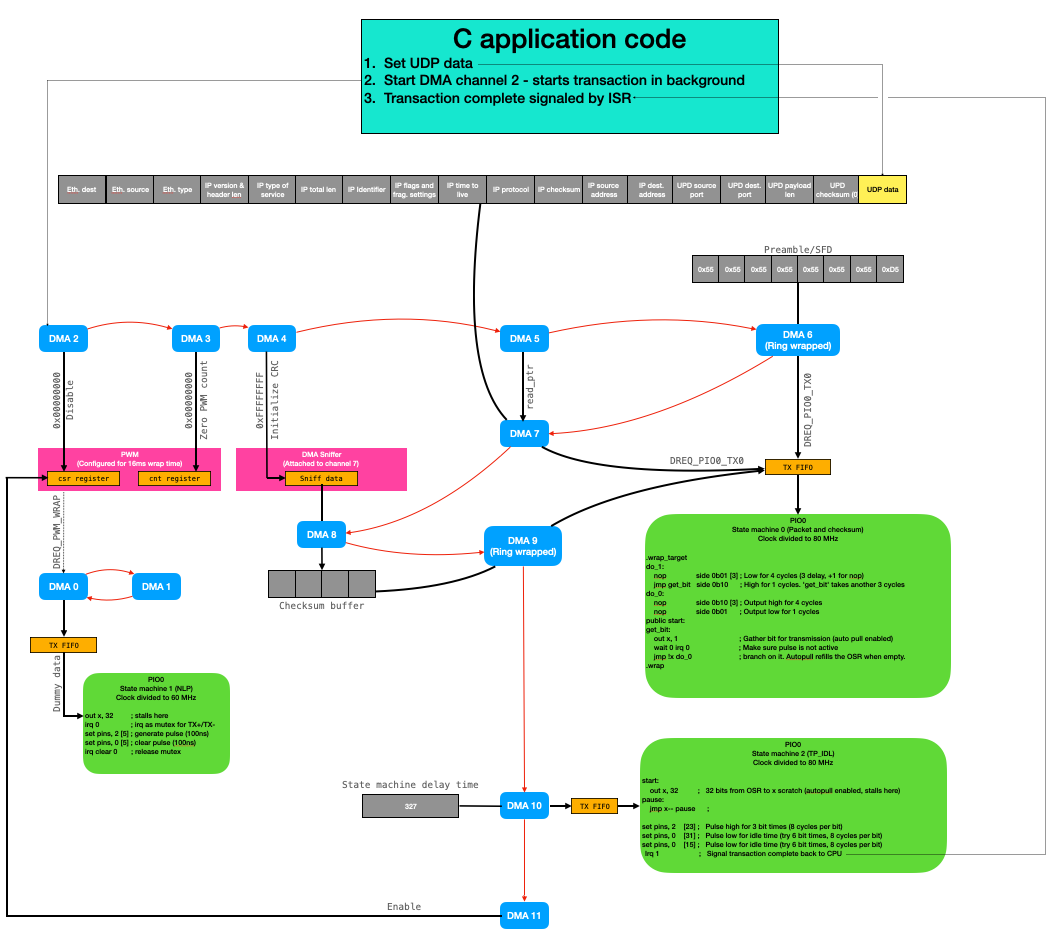
Though the UDP transmitter described on this webpage supports dynamic modification of the source and destination addresses for transactions, it is optimized for static source address, destination address, and payload size. The user configures these parameters, and the only portion of the packet which is modified by the user application code during runtime is the UDP data (which can be done as quickly as the system can modify the values in an array). The user application code modifies this data, and starts DMA channel 2. This initiates a sequence of DMA events that will:
- Stop the PWM channel, so that no normal link pulses are generated during the transaction.
- Zero the PWM counter, so that it counts back up from zero when re-enabled after the transaction (like a watchdog)
- Initializes the DMA sniffer data register.
- Resets the read pointer for the DMA channel which will send the UDP Ethernet packet to PIO state machine 0.
- Sends the preamble/SFD to PIO state machine 0, which serializes it out to the TX+ and TX- pins.
- Sends the UDP Ethernet packet to PIO state machine 0, which serializes it out to the TX+/TX- pins. Note that the DMA sniffer is attached to this channel! So the Ethernet checksum is automatically computed during this transaction, and stored in the
sniffer dataregister. - Moves the checksum (32 bits) to a buffer character array.
- Sends this checksum character array to PIO state machine 0, which serializes it out to PIO state machine 0.
- Sends a delay time to PIO state machine 2, which will wait for the specified amount of time (for the checksum transaction to complete), and then generate the TP_IDL signal. This PIO state machine will also generate an interrupt to signal to the processors that the transaction is complete.
- Re-enables the PWM channel to resume generating the normal link pulse.
This sequence of events is illustrated in the diagram below. Each of the red arrows reads as "chains to." So, you can follow the sequence of events by following the red arrows. Note that DMA channels 0 and 1, which are responsible for interacting with the PIO state machine which generates the normal link pulse, are independent from the other channels. They only see the DREQ generated by the PWM channel. So, this PWM channel is the sole mechanism for interaction between the NLP state machine and the UDP ethernet state machines.
The advantage of all this DMA footwork is that the ethernet transactions are completely non-blocking. For long payloads, this is a really nice feature! User application code can generate the next packet (gather sensor data, perform computations, etc.) while the previous packet is being transmitted. This maximizes the data rate out of the RP2040.
Initializing the UDP packet information
There's a lot of information in a UDP packet, most of which does not need to change from one transmission to the next. The parameters that the user will need to modify are consolidated in udp_tx_parameters.h. The rest of the parameters (which some users may wish to modify for niche applications) are at the very top of udp_tx.h. During initialization, a helper function uses all these parameters to populate an array which includes the ethernet information, IP information, UDP information, and UDP payload in the correct order. The full packet includes:
- Destination MAC address (user specified) - 6 bytes
- Source MAC address (user specified or generated from flash ID) - 6 bytes
- Ethernet type (set to "IP") - 2 bytes
- IP version (v4) and header length (5, for 20 bytes, which is 5 32-bit increments) - 1 byte
- IP type of service - 1 byte
- IP total length - 2 bytes
- IP identifier - 2 bytes
- IP flags and fragmentation settings - 2 bytes
- IP time to live - 1 byte
- IP protocol - 1 byte
- IP checksum - 2 bytes
- IP source address (user specified) - 4 bytes
- IP destination address (user specified) - 4 bytes
- UDP source port (user specified) - 2 bytes
- UDP payload port (user specified) - 2 bytes
- UDP payload length (user specified) - 2 bytes
- UDP checksum (unused, set to 0) - 2 bytes
- UDP payload (user specified data and length)
The checksum is 4 bytes, and is computed from the entire packet above. A DMA sniffer is used to compute this checksum at runtime, and without CPU interaction. In the user application code, the UDP payload can be changed and the checksum will automatically be recomputed during transmission for no overhead.
Generating the Normal Link Pulse
For a 10BASE-T connection, in the absence of network traffic, a pulse must be sent every 16ms +/- 8ms to keep the link alive. In order to implement this, we want something like a watchdog timer. That is, we want for a timer to count down from 16ms and, in the event that it reaches 0, it should trigger an NLP. However, we should have this timer be reset every time we finish sending a packet.
We will use a PIO state machine to generate these pulses, and the state machine will stall on a pull command until a DMA channel moves data into its TX FIFO. The watchdog timer peripheral does not have a DREQ signal visible to the DMA channels, so we'll use a PWM channel as a watchdog!
PWM-based watchdog
The PWM channel is configured with a clock divider of 64 and a wrapval of 60,000. With the system overclocked to 240MHz, this gives a period of 16ms. A DMA channel is configured with DREQ_PWM_WRAP as its DREQ, and it writes to the TX FIFO of the PIO state machine that generates the NLP. This state machine stalls on an out command (with autopull enabled) until the DMA channel puts some dummy data into the FIFO. A second DMA channel is configured to re-enable the first.
To stop the NLP for a transaction, another DMA channel need only to disable the PWM channel. As soon as it is re-enabled and the DREQ starts again, the DMA channel will start triggering NLP's as before.
// Wrapval and clock div for 16ms PWM period
    #define WRAPVAL 60000
    #define CLKDIV  64

    // Slice number chosen arbitrarily
    int slice_num = 7 ;

    // Experimentation shows we don't need to map this to a GPIO
    // or configure a particular duty cycle. Configured for a wraptime
    // of 16ms (NLP interval)
    pwm_set_wrap(slice_num, WRAPVAL) ;
    pwm_set_clkdiv(slice_num, CLKDIV) ;
    pwm_set_enabled(slice_num, true) ;

    ///////////////////////////////////////////////////////////////////
    ////////////////////////// DMA NLP SETUP //////////////////////////
    ///////////////////////////////////////////////////////////////////

    // Triggers the NLP machine, started by PWM watchdog channel
    dma_channel_config c0 = dma_channel_get_default_config(chan_0); // default configs
    channel_config_set_transfer_data_size(&c0, DMA_SIZE_32);        // 32-bit txfers
    channel_config_set_read_increment(&c0, false);                  // no read incrementing
    channel_config_set_write_increment(&c0, false);                 // no write incrementing
    channel_config_set_dreq(&c0, DREQ_PWM_WRAP7) ;                  // DREQ_PWM_WRAP7 pacing
    channel_config_set_chain_to(&c0, chan_1);                       // chain to chan 1

    dma_channel_configure(
        chan_0,                // Channel to be configured
        &c0,                   // The configuration we just created
        &pio->txf[sm_nlp],     // write address (NLP PIO TX FIFO)
        &nlp_dummy,            // The initial read address (dummy value)
        1,                     // Number of transfers; in this case each is 4 byte.
        false                  // Don't start immediately.
    );

    // Channel One (resets NLP pulse machine)
    dma_channel_config c1 = dma_channel_get_default_config(chan_1);  // default configs
    channel_config_set_transfer_data_size(&c1, DMA_SIZE_32);         // 32-bit txfers
    channel_config_set_read_increment(&c1, false);                   // no read incrementing
    channel_config_set_write_increment(&c1, false);                  // no write incrementing
    channel_config_set_chain_to(&c1, chan_0);                        // chain back to chan 0

    dma_channel_configure(
        chan_1,            // Channel to be configured
        &c1,               // The configuration we just created
        &dummy_dest,       // write address (dummy)
        &dummy_source,     // The initial read address (dummy)
        1,                 // Number of transfers; in this case each is 4 byte.
        false              // Don't start immediately.
    );
PIO state machine
The NLP PIO state machine simply stalls on an out command, then sets the TX+/TX- pins for 100ns, and puts the lines back to idle. irq 0 is used to prevent the packet serializing state machine from attempting to take control of the data lines in the middle of a normal link pulse.
    out x, 32           ;   32 bits from OSR to x scratch (autopull enabled, stalls here)
    irq 0               ;   Assert interrupt 0
    set pins, 2 [5]     ;   Pulse for 100 ns
    set pins, 0 [5]     ;   End pulse (both lines idle)
    irq clear 0         ;   Clear interrupt 0
Transmitting the UDP packet
When the user initiates a UDP transfer, a sequence of DMA events occur which move the preamble, SFD, ethernet information, IP information, UDP information, UDP data, and ethernet checksum from memory to a PIO state machine which manchester encodes each bit and puts it out onto the TX+ and TX- pins. All of this happens separately from the ARM processors (i.e., it's non-blocking) so that the user's application code can start computing the next packet while the previous one is being transmitted.
This section briefly summarizes this sequence of DMA events.
Disabling the PWM watchdog
When the user initiates a transfer, disabling and resetting the PWM watchdog is the first thing that happens. This prevents the NLP from being generated during a transmission. To disable the watchdog, DMA channel 2 writes to the csr register of the particular PWM slice that is being used to generate DREQ signals. It writes all zeroes to this register, which disables all PWM channels. For a user application that required a PWM channel to remain active, the value written to this register would be modified to only turn off one slice in particular.
DMA channel 2 chains to DMA channel 3, which writes to the ctr register of the PWM slice which was just disabled. It zeroes the counter so that, when the PWM is re-enabled after the UDP transmission, the counter begins counting up from zero rather than wherever it left off when we disabled the channel. DMA channel 3 then chains to channel 4, which resets the sniffer accumulator.
// Disable the PWM channel
    dma_channel_config c2 = dma_channel_get_default_config(chan_2);  // default configs
    channel_config_set_transfer_data_size(&c2, DMA_SIZE_32);         // 32-bit txfers
    channel_config_set_read_increment(&c2, false);                   // no read incrementing
    channel_config_set_write_increment(&c2, false);                  // no write incrementing
    channel_config_set_chain_to(&c2, chan_3);                        // chain to channel 3

    dma_channel_configure(
        chan_2,                                 // Channel to be configured
        &c2,                                    // The configuration we just created
        &pwm_hw->slice[slice_num].csr,          // write address (csr reg of pwm)
        &pwm_kill,                              // The initial read address (zero variable)
        1,                                      // Number of transfers; in this case each is 4 byte.
        false                                   // Don't start immediately.
    );

    // Zero PWM counter
    dma_channel_config c3 = dma_channel_get_default_config(chan_3);  // default configs
    channel_config_set_transfer_data_size(&c3, DMA_SIZE_32);         // 32-bit txfers
    channel_config_set_read_increment(&c3, false);                   // no read incrementing
    channel_config_set_write_increment(&c3, false);                  // no write incrementing
    channel_config_set_chain_to(&c3, chan_4);                        // chain to channel 4

    dma_channel_configure(
        chan_3,                                 // Channel to be configured
        &c3,                                    // The configuration we just created
        &pwm_hw->slice[slice_num].ctr,          // write address (pwm counter register)
        &pwm_counter_reset,                     // The initial read address (zero variable)
        1,                                      // Number of transfers; in this case each is 4 byte.
        false                                   // Don't start immediately.
    );
Reset the sniffer accumulator
The DMA sniffer will compute a checksum on data that passes through the FIFO of a specified DMA channel. The checksum includes information about each byte as it passes through the FIFO and, as such, it must be reset between transactions. DMA channel 4 writes to the sniff_data register to initialize it for the next transaction. In particular, it initializes it with a value of 0xFFFFFFFF. DMA channel 4 then chains to channel 5.
// Reset the sniffer accumulator
    dma_channel_config c4 = dma_channel_get_default_config(chan_4); // default configs
    channel_config_set_transfer_data_size(&c4, DMA_SIZE_32);        // 32-bit txfers
    channel_config_set_read_increment(&c4, false);                  // no read incrementing
    channel_config_set_write_increment(&c4, false);                 // no write incrementing
    channel_config_set_chain_to(&c4, chan_5);                       // chain to channel 5

    dma_channel_configure(
        chan_4,                // Channel to be configured
        &c4,                   // The configuration we just created
        &dma_hw->sniff_data,   // write address (sniffer data reg)
        &sniff_init,           // The initial read address (variable containing 0xffffffff)
        1,                     // Number of transfers; in this case each is 4 byte.
        false                  // Don't start immediately.
    );
Reset the packet read pointer
The UDP payload is of a user-specified (but fixed) length. As such, we cannot make any assumptions about its length. We cannot use the ring-wrap feature of the DMA channel to reset the read pointer of the DMA channel which moves the packet over to the PIO state machine which puts it onto the pins. We must therefore reset the read pointer of the DMA channel which moves the packet to the PIO state machine (DMA channel 7) between each transaction. DMA channel 5 accomplishes this by writing to the read_addr register of DMA channel 7. In particular, it writes a pointer to the address of the start of the Ethernet packet that we would like to transmit. DMA channel 5 chains to channel 6.
// Reset packet read pointer
    dma_channel_config c5 = dma_channel_get_default_config(chan_5);  // default configs
    channel_config_set_transfer_data_size(&c5, DMA_SIZE_32);         // 32-bit txfers
    channel_config_set_read_increment(&c5, false);                   // no read incrementing
    channel_config_set_write_increment(&c5, false);                  // no write incrementing
    channel_config_set_chain_to(&c5, chan_6);                        // chain to channel 6

    dma_channel_configure(
        chan_5,                                 // Channel to be configured
        &c5,                                    // The configuration we just created
        &dma_hw->ch[chan_7].read_addr,          // write address (dma 7 read address)
        &assembled_packet_pointer,              // The initial read address (pointer to address)
        1,                                      // Number of transfers; in this case each is 4 byte.
        false                                   // Don't start immediately.
    );
Send the preamble/SFD
Channel 6 moves data from an 8-byte array in memory to the PIO state machine which manchester encodes each bit before moving it to the TX+/TX- pins. This array contains the preamble (alternating zeroes and ones), followed by the start frame delimiter. These bytes are stored separately from the rest of the packet for two reasons. The first is that they do not contribute to the ethernet checksum calculation, and so it's convenient to have them transmitted by a separate DMA channel (so that we don't need to toggle the sniffer on and off). Secondly, the preamble/SFD is 8 bytes long, so we can ring-wrap the DMA read pointer to save ourselves an additional DMA channel for resetting this pointer.
Note that the DMA transactions are paced by the DREQ_PIO0_TX0 data request flag. Channel 6 chains to channel 7.
// Do preamble transaction (8 bytes long, ring wrap to avoid a read pointer reset)
    dma_channel_config c6 = dma_channel_get_default_config(chan_6); // default configs
    channel_config_set_transfer_data_size(&c6, DMA_SIZE_8);         // 8-bit txfers
    channel_config_set_read_increment(&c6, true);                   // yes read incrementing
    channel_config_set_write_increment(&c6, false);                 // no write incrementing
    channel_config_set_ring(&c6, false, 3) ;                        // ring wrap read address!
    channel_config_set_dreq(&c6, DREQ_PIO0_TX0) ;                   // DREQ_PIO0_TX0 pacing (FIFO)
    channel_config_set_chain_to(&c6, chan_7);                       // chain to channel 7

    dma_channel_configure(
        chan_6,                 // Channel to be configured
        &c6,                    // The configuration we just created
        &pio->txf[sm_tx],       // write address (TX FIFO for packet serializer PIO)
        &preamble[0],           // The initial read address (pointer to character array)
        PREAMBLE_LEN,           // Number of transfers; in this case each is 1 byte.
        false                   // Don't start immediately.
    );
The same PIO state machine is used to manchester-encode and serialize the preamble/SFD, packet, and checksum. That state machine is included below. The machine will stall on the out x, 1 command until data appears in the TX FIFO. That out command will then shift one bit from the OSR (autopull is enabled, so data automatically moves from the TX FIFO to the OSR) to the x scratch register. The state machine waits on an irq to confirm that there is not presently an NLP, then either jumps to either the do_0 location or wraps to the do_1 location depending if the value of the bit is a zero or a one. If it is a zero, then the state machine puts a high to low transmission on the TX+/TX- lines. Otherwise, it puts a low-to-high transmission on the lines. Thus, the state machine manchester encodes all bits that it receives, and puts them out differentially on TX+ and TX-.
.wrap_target
do_1:
    nop         side 0b01 [3] ; Low for 3 cycles (2 delay, +1 for nop)
    jmp get_bit side 0b10     ; High for 1 cycles. 'get_bit' takes another 2 cycles
do_0:
    nop         side 0b10 [3] ; Output high for 3 cycles
    nop         side 0b01     ; Output low for 1 cycles
public start:
get_bit:
    out x, 1               ; Always shift out one bit from OSR to X, so we can
    wait 0 irq 0           ; Make sure pulse is not active
    jmp !x do_0            ; branch on it. Autopull refills the OSR when empty.
.wrap
Send the packet
Channel 7 steps through the UPD ethernet packet stored in memory and sends it, byte by byte, to the PIO state machine which manchester encodes it and serializes it out to the TX+/TX- pins. The sniffer is enabled for this channel, so that a checksum is computed on all the bytes communicated by this channel to the PIO state machine. This sniffer is highly configurable, and finding the correct configuration took some trial and error. I used this webpage as a resource.
The particular set of sniffer settings that ended up working involved inverting the output bits, and reversing the output bits. This led to the correct checksum being computed and stored in the sniff_data register, but in byte-reversed order. DMA channel 8, chained to by channel 7, solved that problem.
dma_channel_config c7 = dma_channel_get_default_config(chan_7); // default configs
    channel_config_set_transfer_data_size(&c7, DMA_SIZE_8);         // 8-bit txfers
    channel_config_set_read_increment(&c7, true);                   // yes read incrementing
    channel_config_set_write_increment(&c7, false);                 // no write incrementing
    channel_config_set_dreq(&c7, DREQ_PIO0_TX0) ;                   // DREQ_PIO0_TX0 pacing (FIFO)
    channel_config_set_chain_to(&c7, chan_8);                       // chain to channel 8

    dma_channel_configure(
        chan_7,                 // Channel to be configured
        &c7,                    // The configuration we just created
        &pio->txf[sm_tx],       // write address (TX FIFO for packet serializer PIO)
        &assembled_packet[0],   // The initial read address (pointer to packet array)
        PACKET_LEN,             // Number of transfers; in this case each is 1 byte.
        false                   // Don't start immediately.
    );

    // Configure the sniffer! Rather tricky setup, this is what worked.
    dma_sniffer_enable(chan_7, 1, true);
    hw_set_bits(&dma_hw->sniff_ctrl, (DMA_SNIFF_CTRL_OUT_INV_BITS | DMA_SNIFF_CTRL_OUT_REV_BITS));
Move checksum to byte array
The sniffed checksum appears in the 32-bit sniff_data register, but we want to communicate the checksum to the PIO state machine one byte at a time. In order to do this, it's convenient to move the checksum to a 4-element character array before moving it from the character array to the PIO. DMA channel 8 performs a 32-bit transaction from the sniff_data register to the first element of the character array. Because we are doing a 32-bit transaction to an array of 4 chars, this reverses the bytes (solving the byte reversal problem from earlier).
// Send sniffed CRC to character array
    dma_channel_config c8 = dma_channel_get_default_config(chan_8); // default configs
    channel_config_set_transfer_data_size(&c8, DMA_SIZE_32);        // 32-bit txfers
    channel_config_set_read_increment(&c8, false);                  // no read incrementing
    channel_config_set_write_increment(&c8, false);                 // no write incrementing
    channel_config_set_bswap(&c8, false);                           // not necessary b/c char array
    channel_config_set_chain_to(&c8, chan_9);                       // chain to channel 9

    dma_channel_configure(
        chan_8,                // Channel to be configured
        &c8,                   // The configuration we just created
        &crc_dest[0],          // write address (checksum buffer character array)
        &dma_hw->sniff_data,   // The initial read address (DMA sniffer data)
        1,                     // Number of transfers; in this case each is 4 byte.
        false                  // Don't start immediately.
    );
Send the checksum
DMA channel 9, chained to by channel 8, moves the checksum from the character array to the PIO state machine. Ring wrapping is used for this DMA channel also, since the byte array is of length 4 (a power of two), saving us an additional DMA channel for resetting a read pointer.
// Send sniffed character array to PIO (use ring wrap to avoid a reset channel)
    dma_channel_config c9 = dma_channel_get_default_config(chan_9); // default configs
    channel_config_set_transfer_data_size(&c9, DMA_SIZE_8);         // 8-bit txfers
    channel_config_set_read_increment(&c9, true);                   // yes read incrementing
    channel_config_set_write_increment(&c9, false);                 // no write incrementing
    channel_config_set_ring(&c9, false, 2) ;                        // ring wrap read addrsses!
    channel_config_set_dreq(&c9, DREQ_PIO0_TX0) ;                   // DREQ_PIO0_TX0 pacing (FIFO)
    channel_config_set_chain_to(&c9, chan_10);                      // chain to channel 10

    dma_channel_configure(
        chan_9,                 // Channel to be configured
        &c9,                    // The configuration we just created
        &pio->txf[sm_tx],       // write address (TX FIFO for packet serializer PIO)
        &crc_dest[0],           // The initial read address (pointer to checksum array)
        CRC_LEN,                // Number of transfers; in this case each is 1 byte.
        false                   // Don't start immediately.
    );
Trigger TP_IDL
Each transmission ends with a TP_IDL signal (a positive pulse of about 3 bit-times, followed by an idle period). A separate PIO state machine generates this signal.
// Trigger a TP_IDL pulse (another PIO machine)
    dma_channel_config c10 = dma_channel_get_default_config(chan_10);   // default configs
    channel_config_set_transfer_data_size(&c10, DMA_SIZE_32);           // 32-bit txfers
    channel_config_set_read_increment(&c10, false);                     // no read incrementing
    channel_config_set_write_increment(&c10, false);                    // no write incrementing
    channel_config_set_dreq(&c10, DREQ_PIO0_TX2) ;                      // DREQ_PIO0_TX2 pacing
    channel_config_set_chain_to(&c10, chan_11);                         // chain to channel 11

    dma_channel_configure(
        chan_10,                // Channel to be configured
        &c10,                   // The configuration we just created
        &pio->txf[sm_idl],      // write address (TP_IDL PIO state machine TX fifo)
        &idl_delay,             // The initial read address (variable holding wait time)
        1,                      // Number of transfers; in this case each is 4 byte.
        false                   // Don't start immediately.
    );
This PIO state machine stalls on an out command until DMA channel 10, chained to by DMA channel 9, puts some data into its TX FIFO. The state machine then waits for the checksum to complete before generating the TP_IDL signal. It stalls in the pause state while decrementing scratch register x, then generates the pulse, and sets the pins to an idle state for about 64 bit times. The state machine then uses irq 1 to send an interrupt back to the CPU, signalling that the transmission has completed.
start:
    out x, 32          ;   32 bits from OSR to x scratch (autopull enabled, stalls here)
pause:
    jmp x-- pause      ;

set pins, 2    [23] ;   Pulse high for 3 bit times (8 cycles per bit)
set pins, 0    [31] ;   Pulse low for idle time
set pins, 0    [31] ;
set pins, 0    [31] ;
set pins, 0    [31] ;
set pins, 0    [31] ;
set pins, 0    [31] ;
set pins, 0    [31] ;
set pins, 0    [31] ;
set pins, 0    [31] ;
set pins, 0    [31] ;
set pins, 0    [31] ;
set pins, 0    [31] ;
set pins, 0    [31] ;
set pins, 0    [31] ;
set pins, 0    [31] ;
set pins, 0    [31] ;
irq 1               ;   Signal transaction complete to CPU
Re-enabling the PWM watchdog
Finally, DMA channel 11 revives the PWM watchdog by writing to the csr register. The PWM channel will resume generating DREQ signals which will be consumed by DMA channel 0 to initiate NLP's.
// Revive the PWM channel after packet transaction
    dma_channel_config c11 = dma_channel_get_default_config(chan_11);   // default configs
    channel_config_set_transfer_data_size(&c11, DMA_SIZE_32);           // 32-bit txfers
    channel_config_set_read_increment(&c11, false);                     // no read incrementing
    channel_config_set_write_increment(&c11, false);                    // no write incrementing

    dma_channel_configure(
        chan_11,                           // Channel to be configured
        &c11,                              // The configuration we just created
        &pwm_hw->slice[slice_num].csr,     // write address (pwm csr register)
        &pwm_revive,                       // The initial read address (1 variable)
        1,                                 // Number of transfers; in this case each is 4 byte.
        false                              // Don't start immediately.
    );