How does a rotary encoder work?
V. Hunter Adams
Purpose of this webpage
In ECE 4760, you are asked to use a rotary encoder to implement a user interface to one of your labs. This webpage will not provide a wiring guide or demo code, but will instead give you the background knowledge that, by applying the stuff we've learned in previous labs, allows you to put together some code for interacting with the encoder.
Think carefully about your design! The lab for which you're using the rotary encoder is all about optimization. You want to spend as few cycles as possible interacting with the rotary encoder and as many cycles as possible doing animation calculations. Hmm, does an interrupt-based interface seem like a good approach? Maybe this demo code could be useful??
How do rotary encoders work?
The rotary encoder that we'll be using has three pins on one side and two pins on the other. Those two pins are just the output of a normally-open switch. When you push down on the top of the potentiometer, it shorts those two pins together.
The side with three pins is more interesting. These pins are called A, B and COM. As you rotate the encoder with your fingers, you're rotating an internal disk that contains evenly-spaced "contact zones." Each of these contact zones is connected to the COM pin. So, if you were to connect COM to ground, each of these contact zones would also be connected to ground. See the image below.
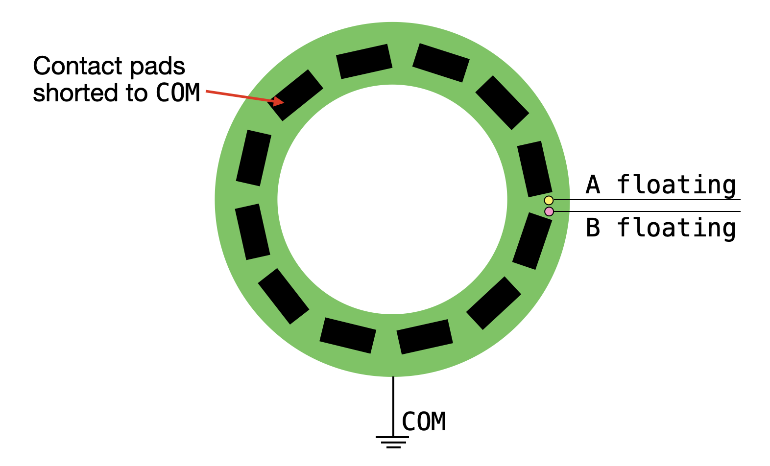
The A and B pins connect to contacts that do not rotate along with the internal disk. Instead, the disk rotates underneath the contacts. The rotating contact zones make contact with A and B as they rotate underneath them. When this happens, COM shorts to A and/or B. The output pins associated with A and B float when they are not shorted to a contact zone.
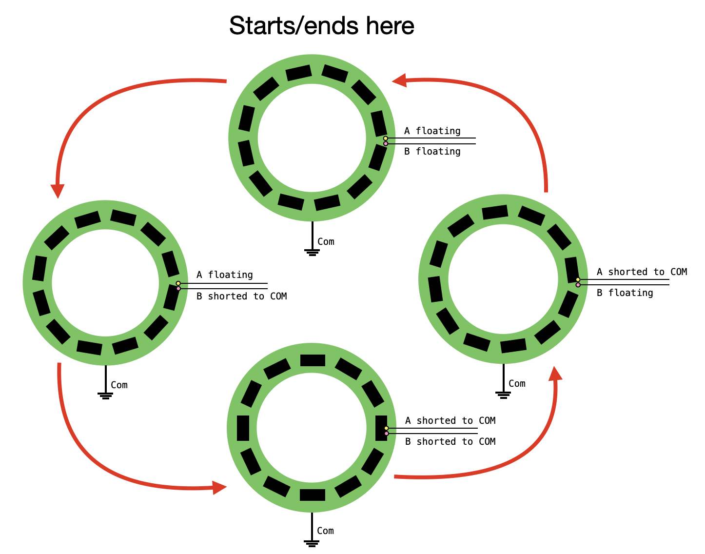
The internal contacts for A and B are oriented such that, as you rotate clockwise by one "click," the next contact pad on the internal disk will be rotated into contact with A first, then it will be in contact with A and B, then it will only be in contact with B, and then it will again be out of contact with both A and B.
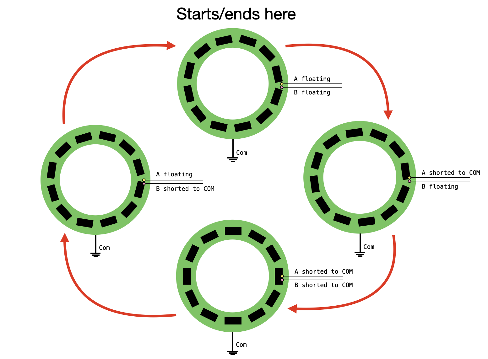
Does it stand to reason that rotating counterclockwise by one "click" gives the same events in opposite order?