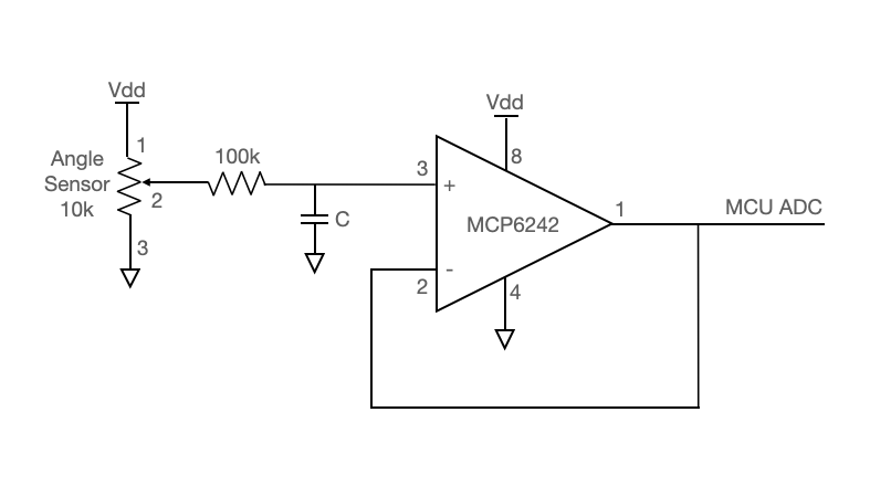
The circuit
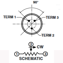
The angle sensor is a 10k low-torque potentiometer. The potentiometer output passes through an anti-aliasing low-pass filter (with R and C chosen as appropriate for a 1KHz sample rate) and into the MCP6242 opamp. This opamp is configured in as a unity-gain buffer, the output from which goes into the RP2040 ADC.
Setting up the ADC
In this lab, you will be reading the ADC in an interrupt-service routing using software (as opposed to a DMA channel). This will require that you initialize the ADC in main. The first line initializes the ADC, and the second selects the ADC input. There are 4 possible inputs on GPIO's 26, 27, 28, 29. The fifth input is an internal temperature sensor.
adc_init() ;
adc_select_input(0) ;
We will read the ADC in the ISR, as shown below. The ADC returns a 12-bit number. Reading the ADC takes 96 cycles of the ADC clock, which runs at 48MHz.
// Read the ADC (in the range [0, 4096]. Twelve bits.)
// This is blocking, and takes 96 cycles of the ADC clock.
adc_output = adc_read() ;
Testing and debugging
- Before attaching the opamp output to the ADC input of the microcontroller, scope it!! Confirm that the voltages are changing as the potentiometer rotates