Introduction
This webpage describes a method for interfacing a 3x4 matrix keypad, like the one pictured in Fig. 1, with an RP2040. Other methods for building this interface exist (this would be a nice application for the PIO coprocessors, for instance). The particular method described on this page is the one that I think is most educationally useful in ECE 4760.
This webpage explains what is happening in this example code.
Keypad Layout
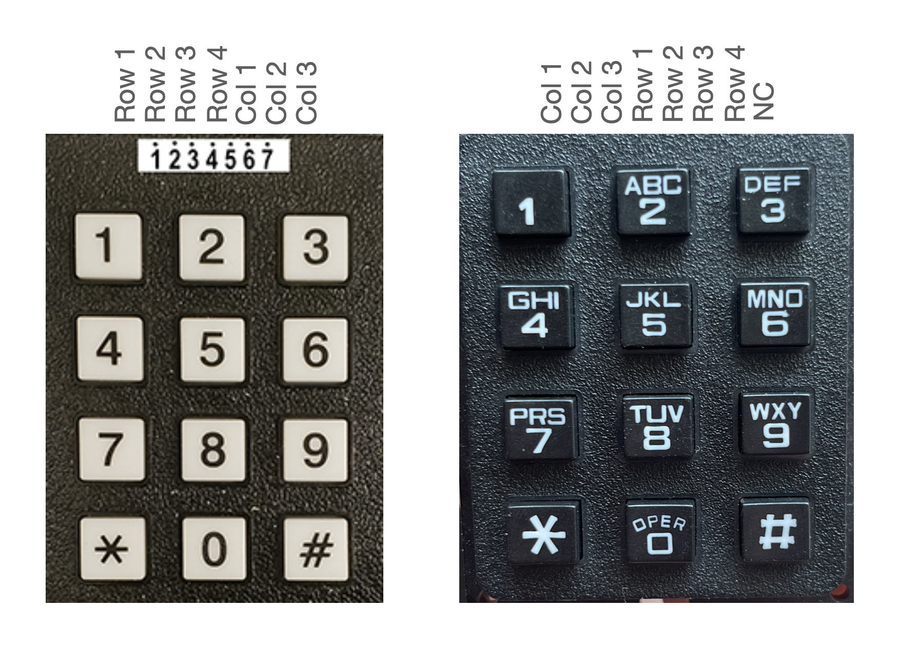
The 3x4 keypad has 7 pinouts. Four of these pins are connected to each row of the keypad, and the remaining three pins are connected to each column of the keypad. Pressing a key shorts one of these pins to another of the pins. For example, pressing the 1 key shorts the pin attached to row 1 to the pin attached to column 1.
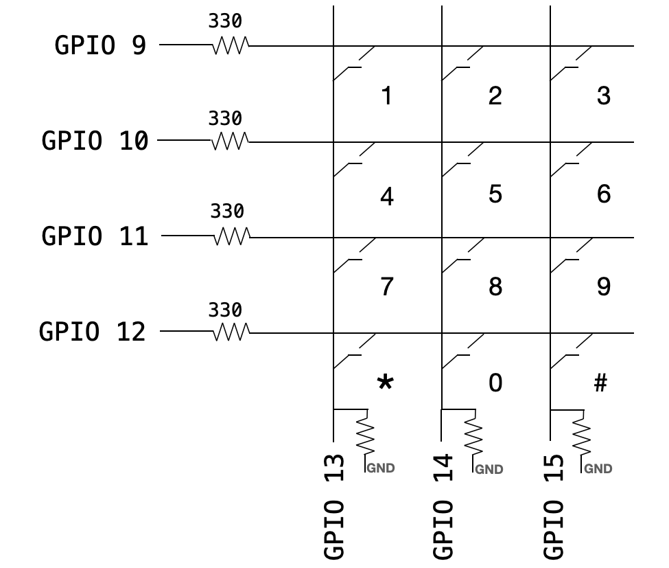
Fig. 2 illustrates this internal layout, and indicates the particular RP2040 GPIO pins to which each pin is attached by default in the keypad demo code.
Reading the keypad
Configuring GPIO's
To scan the keypad for button presses, we will configure each of the GPIO's connected to the rows of the keypad (9-12, as shown in Fig. 2) as outputs, and we'll configure each of the GPIO's connected to the columns of the keypad (13-15, as shown in Fig. 2) as inputs. For each of the input pins, we will enable internal pullup resistors. To start, we'll set all the output GPIO's attached high.
Using the C SDK for the RP2040, all of these configurations look like the following:
#define BASE_KEYPAD_PIN 9

// Initialize the keypad GPIO's
gpio_init_mask((0x7F << BASE_KEYPAD_PIN)) ;
gpio_set_dir((BASE_KEYPAD_PIN+4), GPIO_IN) ;
gpio_set_dir((BASE_KEYPAD_PIN+5), GPIO_IN) ;
gpio_set_dir((BASE_KEYPAD_PIN+6), GPIO_IN) ;
// Set row-pins to output
gpio_set_dir_out_masked((0xF << BASE_KEYPAD_PIN)) ;
// Set all output pins to low
gpio_put_masked((0xF << BASE_KEYPAD_PIN), (0x0 << BASE_KEYPAD_PIN)) ;
// Turn on pulldown resistors for column pins (on by default)
gpio_pull_up((BASE_KEYPAD_PIN + 4)) ;
gpio_pull_up((BASE_KEYPAD_PIN + 5)) ;
gpio_pull_up((BASE_KEYPAD_PIN + 6)) ;
Scanning for presses
The RP2040 allows for us to get the state of all of the GPIO ports using gpio_get_all(). This returns a 32-bit unsigned int, each bit of which represents the state (high or low) of the associated GPIO port (bit 0 is GPIO 0, bit 1 is GPIO 1, etc.).
We scan the keypad by setting the GPIO's attached to the columns of the matrix low one at a time, and then reading the states of all 7 GPIO's that are attached to the keypad. For convenience, we'll call gpio_get_all(), then shift the result right by 9 (so that the state of GPIO 9 is in bit 0), and then mask with 0x7f. This way, we're left with a 7-bit number, where each bit in that number represents one of the pins of the keypad. The first four are attached to the rows, and the next 3 are attached to the columns.
keypad = ((gpio_get_all() >> BASE_KEYPAD_PIN) & 0x7F) ;
Suppose that we clear GPIO 9, and we are not presssing any keys. Then none of the column pins are shorted to the row pins, and they'd all remain pulled high. The bit associated with GPIO 9 will be low (since we set it low), but none of the others. So, when we scan the keypad, we get a value of 0b1111110, or 0x7E. This is the scancode that corresponds to "no press."
Suppose instead that we set GPIO 9 low, and we press key 1. What value would we expect for the keypad? The bit associated with GPIO 9 will be low (since we set it low), and the bit associated with GPIO 13 will also be low, since pressing key 1 shorted it to GPIO 9. So, the binary value for keypad will be 0b1101110, or 0x6E in hex.
Suppose that we had instead pressed 2. Then the bits of keypad associated with GPIO's 9 and 14 would be low. We would get a scancode of 0b1011110, or 0x5E.
And lastly, suppose that we had pressed 3. Then the bits of keypad associated with GPIO's 9 and 15 would be low. We would get a scancode of 0b0111110, or 0x3E.
If we had gotten any scancode other than 0x7E, 0x6E, 0x5E, or 0x3E, then that means the user had two keys pressed simultaneously. You could expand your keycodes to accomodate those cases, but for now we'll treat these as "invalid presses."
The table below enumerates these cases for row 0, and expands to include the scancodes for the other three rows of the keypad.
| GPIO 15 | GPIO 14 | GPIO 13 | GPIO 12 | GPIO 11 | GPIO 10 | GPIO 9 | Control code | Scancode | Interpretation | |
|---|---|---|---|---|---|---|---|---|---|---|
| 1 | 1 | 1 | 1 | 1 | 1 | 0 | 0xE | 0x07 | No press | |
| 1 | 1 | 0 | 1 | 1 | 1 | 0 | 0x6E | Pressed x | ||
| 1 | 0 | 1 | 1 | 1 | 1 | 0 | 0x5E | Pressed 2 | ||
| 0 | 1 | 1 | 1 | 1 | 1 | 0 | 0x3E | Pressed 3 | ||
| 1 | 1 | 1 | 0 | else | Invalid. | |||||
| 1 | 1 | 1 | 1 | 1 | 0 | 1 | 0xD | 0x07 | No press | |
| 1 | 1 | 0 | 1 | 1 | 0 | 1 | 0x6D | Pressed 4 | ||
| 1 | 0 | 1 | 1 | 1 | 0 | 1 | 0x5D | Pressed 5 | ||
| 0 | 1 | 1 | 1 | 1 | 0 | 1 | 0x3D | Pressed 6 | ||
| 1 | 1 | 0 | 1 | else | Invalid. | |||||
| 1 | 1 | 1 | 1 | 0 | 1 | 1 | 0xB | 0x07 | No press | |
| 1 | 1 | 0 | 1 | 0 | 1 | 1 | 0x6B | Pressed 7 | ||
| 1 | 0 | 1 | 1 | 0 | 1 | 1 | 0x5B | Pressed 8 | ||
| 0 | 1 | 1 | 1 | 0 | 1 | 1 | 0x3B | Pressed 9 | ||
| 1 | 0 | 1 | 1 | else | Invalid. | |||||
| 1 | 1 | 1 | 0 | 1 | 1 | 1 | 0x7 | 0x07 | No press | |
| 1 | 1 | 0 | 0 | 1 | 1 | 1 | 0x67 | Pressed * | ||
| 1 | 0 | 1 | 0 | 1 | 1 | 1 | 0x57 | Pressed 0 | ||
| 0 | 1 | 1 | 0 | 1 | 1 | 1 | 0x37 | Pressed # | ||
| 0 | 1 | 1 | 1 | else | Invalid. |
Note that we can do a quick check to see whether or not any button is pushed by masking ~keypad with 0x70, and checking if the result is nonzero. If the result is nonzero, it means one or more of the column GPIO's (15, 14, and/or 13) is pressed. We can then compare the full scancode against valid scancodes to determine which button was pressed.
Encoded, this sequence of steps looks like the following:
#define BASE_KEYPAD_PIN 9
#define KEYROWS         4
#define NUMKEYS         12

unsigned int keycodes[NUMKEYS] = {   0x57, 0x6E, 0x5E, 0x3E, 0x6D,
                                0x5D, 0x3D, 0x6B, 0x5B, 0x3B,
                                0x67, 0x37} ;
unsigned int scancodes[KEYROWS] = {   0xE, 0xD, 0xB, 0x7} ;
unsigned int button = 0x70 ;

// Scan the keypad!
for (i=0; i<KEYROWS; i++) {
    // Set a row high
    gpio_put_masked((0xF << BASE_KEYPAD_PIN),
                    (scancodes[i] << BASE_KEYPAD_PIN)) ;
    // Small delay required
    sleep_us(1) ;
    // Read the keycode
    keypad = ((gpio_get_all() >> BASE_KEYPAD_PIN) & 0x7F) ;
    // Break if button(s) are pressed
    if ((~keypad) & button) break ;
}
// If we found a button . . .
if ((~keypad) & button) {
    // Look for a valid keycode.
    for (i=0; i<NUMKEYS; i++) {
        if (keypad == keycodes[i]) break ;
    }
    // If we don't find one, report invalid keycode
    if (i==NUMKEYS) (i = -1) ;
}
// Otherwise, indicate invalid/non-pressed buttons
else (i=-1) ;
After the above code executes, the value of i will be -1 for no press or invalid press, and otherwise it will have the value of the key pressed (with 10 for * and 11 for #).
Debouncing
Each button on the keypad can be modeled as a spring-mass-damper system. When you press a key, you are closing a mechanical switch, and mechanical things bounce! As a consequence, the microcontroller might detect multiple button presses each time you press/release a key. In order to prevent this, you must implement a debouncing state machine. An example of one such state machine is illustrated in Fig. 3.
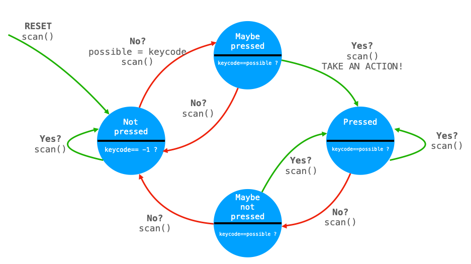
We start in the Not pressed state and repeatedly scan the keypad for a button press. For as long as that scan returns no press or invalid press, we remain in the Not pressed state.
When the scan returns a valid keypress, we transition to the Maybe pressed state and store the value of that keypress in a variable called possible. We then scan the keypad again, and compare the keycode to the value of possible. If they differ, then the key has bounced to a different state and we transition back to Not pressed. If they are the same, then we assume the key state to be stable and we transition from Maybe pressed to Pressed. If you want for a single event to occur each time a button is pressed, then that event should be triggered on this transition.
Once we're in the Pressed state, we continue to scan the keypad. For as long as the keycode matches the value that we stored in possible, we remain in this state. If the value differs, we transition to Maybe not pressed.
In Maybe not pressed, we scan the keypad again. If the keycode matches possible, we transition back to Pressed. Otherwise, we transition to Not pressed.
Why do we pulse the rows low instead of high?
Why pull the columns up instead of down? In principle either works just fine, but this design is compatible with Errata RP2350-E9.