PIO-Driven Stepper Motor Driver
V. Hunter Adams (vha3@cornell.edu)
Projects homepage
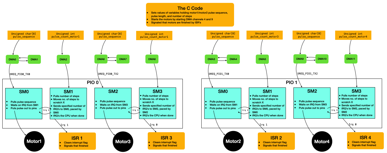
Code Organization
This motor driver uses the PIO state machines and DMA channels on the RP2040 to offload driving two stepper motors (ULN2003's) from the CPU. The user sets each motor's direction, speed, and the number of steps to execute in code then starts the driver. The motor will execute the specified number of steps at the specified speed and in the specified direction, then throw an interrupt back to the CPU. This is all non-blocking, so the CPU can carry on while the motor is moving. The driver supports dynamic modification of speed and direction during a maneuver.
PIO Stepper Drivers
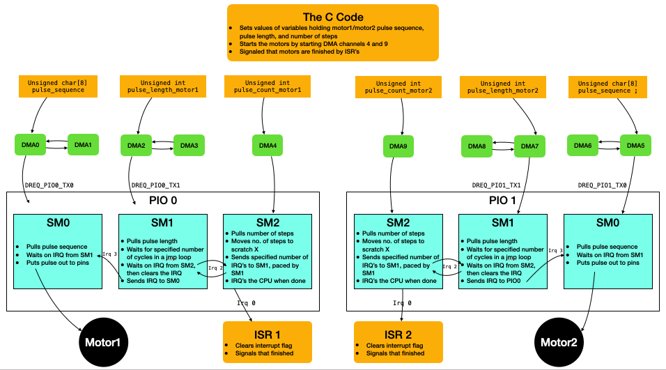
The subsections below describe each of the three PIO state machines loaded onto each PIO block. Because IRQ0 has a different interrupt flag for each PIO block, all three of these state machines can be loaded, without modification, onto each core separately. We then simply setup separate interrupt service routines for each IRQ0.
Step counting state machine
The step counting state machine (SM2 in the above flow chart) is responsible for controlling the number of steps executed by the motor, and for interrupting back to the CPU when the motor has completed its maneuver. It first pulls the commanded number of steps from the FIFO to the OSR, and then moves that value from the OSR to the X scratch register. In countloop, the state machine signals to the pulse length state machine to start a new pulse, waits for the pulse length state machine to signal that it has started that pulse, and then decrements X. It will continue to signal the pulse length state machine until X is zero, at which point it will send an interrupt to the CPU that all commanded steps have been executed. The state machine waits for the CPU to clear this interrupt, and then pulls a new commanded number of steps.
pull block                   ; Copy commanded # of steps from FIFO to OSR
mov x, osr                   ; Copy value from OSR to scratch X

countloop:
   irq wait 2               ; Signal for a step to occur, wait for flag to clear
   jmp x-- countloop        ; Loop until X hits 0

irq wait 0                  ; IRQ to CPU ISR, wait for CPU to clear
The step counting state machine is fed by a DMA channel (DMA 4 on PIO0, and DMA 9 on PIO1). Each of these DMA channels is triggered in software so that the user can start the motors at a particular time in the application. Note that these DMA channels send a 32-bit value to the counter state machines. In principle, this means that a motor could be commanded to execute $2^{32}$ steps which, at the motor's maximum speed, would take ~2 days. For applications that required continuous rotation, the interrupt service routine entered after executing all commanded steps would command a new set of steps.
Pulse length state machine
The speed of the motor is controlled by manipulating the length of a pulse (each pulse causes a step). This PIO state machine throttles the speed at which the pulse generating state machine puts a new pulse out to the motor, causing it to take a step. This state machine uses the autopull feature of the PIO on the RP2040 to avoid a pull instruction. When the OSR is empty, the state machine will automatically pull a new value from the FIFO.
It then moves that value to the X scratch register and delays in a jmp loop for that many cycles. If it has received a signal from the step counting state machine that a step should be taken, then it sends an interrupt to the pulse generating state machine to put a new pulse out onto the pins. In the event that all steps have been completed, then this state machine will stall on the wait 1 irq 2 instruction.
out x, 32                     ; Shift value from OSR to scratch X (AUTOPULL ENGAGED)

countloop:
    jmp x-- countloop        ; Loop until X hits 0

wait 1 irq 2                 ; Wait for signal to pulse from counter state machine
irq 3                        ; Signal to send a pulse
This state machine is fed by a DMA channel that is paced by the PIO_TX DREQ. When the FIFO is empty, a new DMA transfer is automatically initiated. The DMA channel that communicates with the PIO state machine is chained with a second DMA channel that reconfigures and restarts the first. This way, this DMA channel is always providing data to the PIO state machine when it needs it.
The user might change the value at the memory address where the DMA channel is looking to gather data in order to dynamically change the value that is sent to this state machine. By doing so, the speed of the motors can be changed during a maneuver (this was done for the Lorenz and DDS examples shown below).
Pulse generating state machine
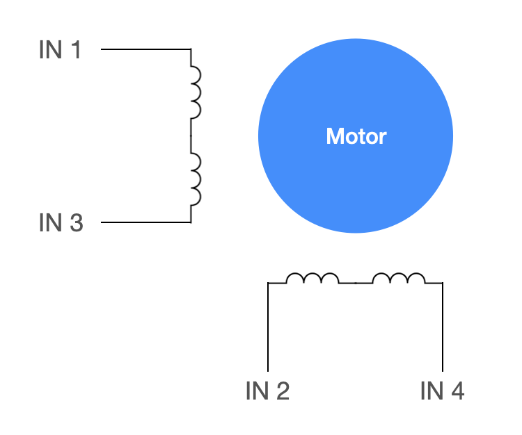
The ULN2003 is a 4-input stepper motor with the internal connections shown below. The motor can be full-stepped or half-stepped, but has greater speed and torque capabilities with half stepping. The half-step switching sequence is shown in the table below.
| IN1 | IN2 | IN3 | IN4 | Hex code | |||
|---|---|---|---|---|---|---|---|
| Half step 1 | HIGH | LOW | LOW | HIGH | 0x09 | ||
| Half step 2 | HIGH | LOW | LOW | LOW | 0x08 | ||
| Half step 3 | HIGH | HIGH | LOW | LOW | 0x0c | ||
| Half step 4 | LOW | HIGH | LOW | LOW | 0x04 | ||
| Half step 5 | LOW | HIGH | HIGH | LOW | 0x06 | ||
| Half step 6 | LOW | LOW | HIGH | LOW | 0x02 | ||
| Half step 7 | LOW | LOW | HIGH | HIGH | 0x03 | ||
| Half step 8 | LOW | LOW | LOW | HIGH | 0x01 |
The PIO state machine that sends this pulse sequence out to the GPIO pins connected to the motor driver is quite simple. It waits for a signal from the pulse length state machine, and then it uses an out instruction to move data from the OSR to 4 output pins (connected to IN1, IN2, IN3, and IN4 of the motor controller). This PIO state machine also has autopull enabled, and it will pull for a new half step state each time it shifts 4 bits out of the OSR.
wait 1 irq 3            ; Wait for signal to put pulse on pins
out pins, 4             ; Put a pulse on the pins, AUTOPULL ENGAGED
Like the other state machines, this one too is fed by a DMA channel. The DMA channel supplies the pulse sequence that will be put onto the pins. It does so 8 bits at a time, by stepping through one of the pulse sequences shown below. The first is the sequence that will yield counterclockwise movement, the second is the reverse sequence that will yield clockwise movement, and the final will yield no movement of the motor. By changing the pointer that the DMA channel is using for gathering data, the user can dynamically change the direction or stop the motor. This too is used to create the Lorenz and DDS curves shown in a later section.
unsigned char pulse_sequence_forward [8]  = {0x9, 0x8, 0xc, 0x4, 0x6, 0x2, 0x3, 0x1} ;
unsigned char pulse_sequence_backward [8] = {0x1, 0x3, 0x2, 0x6, 0x4, 0xc, 0x8, 0x9} ;
unsigned char pulse_sequence_stationary [8] = {0x0, 0x0, 0x0, 0x0, 0x0, 0x0, 0x0, 0x0} ;
API
There is a setup function for each motor. These functions setup and start the DMA channels and interrupt service routines associated with the motor driver. As an argument, each setup function takes the number of the GPIO pin to which IN1 is attached for the stepper driver. It is assumed that IN2 is attached to GPIO number IN1+1, IN3 to GPIO pin IN1+2, and IN4 to GPIO pin IN1+3. The second argument to each setup function is the name of the interrupt handler for the interrupt that will be thrown by the step counting state machine when it finishes a maneuver.
setupMotor1(MOTOR1_IN1, pio0_interrupt_handler) ;
setupMotor2(MOTOR2_IN1, pio1_interrupt_handler) ;
Within the user application, the motors are controlled with a series of macros. SET_DIRECTION_MOTOR_x sets the DMA pointer feeding the pulse generating state machine to the forward pulse sequence, the reverse pulse sequence, or the stopped pulse sequence. SET_SPEED_MOTOR_x sets the value contained at the memory address being accessed by the DMA channel feeding the pulse length state machine. Modifying this value modifies the length of each pulse to the motor, thus changing the motor's speed. Finally, MOVE_STEPS_MOTOR_x sets the value at the memory address being accessed by the DMA channel feeding the step counting state machine, and starts the DMA channel to execute a maneuver.
#define MOVE_STEPS_MOTOR_1(a) pulse_count_motor1=a; dma_channel_start(dma_chan_4)
#define SET_SPEED_MOTOR_1(a) pulse_length_motor1=a
#define SET_DIRECTION_MOTOR_1(a) address_pointer_motor1 = (a==2) ? &pulse_sequence_forward[0] : (a==1) ? &pulse_sequence_backward[0] : &pulse_sequence_stationary[0]

#define MOVE_STEPS_MOTOR_2(a) pulse_count_motor2=a; dma_channel_start(dma_chan_9)
#define SET_SPEED_MOTOR_2(a) pulse_length_motor2=a
#define SET_DIRECTION_MOTOR_2(a) address_pointer_motor2 = (a==2) ? &pulse_sequence_forward[0] : (a==1) ? &pulse_sequence_backward[0] : &pulse_sequence_stationary[0]
With this API, the user can specify the direction a motor should turn, a speed, and a number of steps to execute. The driver will execute the maneuver in a non-blocking manner, and throw an interrupt when the maneuver is complete. Alternatively, this API supports dynamic modification of the motor speed and direction to allow a user to put a motor in free-run mode and dynamically update its speed and direction.
As an example, the code below uses direct digital synthesis to set the motor speeds and directions in a timer interrupt.
bool repeating_timer_callback(struct repeating_timer *t) {

    // DDS phase accumulation
    phase_accum_main += phase_incr_main  ;

    // Sine table lookup (motor 2 90 degrees out of phase)
    sineval = sin_table[phase_accum_main >> 24] ;
    sineval2 = sin_table[((phase_accum_main + 1073741824) >> 24)] ;

    // Determine the motor direction
    motor1_direction = (sineval>0) ? CLOCKWISE : COUNTERCLOCKWISE  ;
    motor2_direction = (sineval2>0) ? CLOCKWISE : COUNTERCLOCKWISE ;

    // Set the motor direction
    SET_DIRECTION_MOTOR_1(motor1_direction) ;
    SET_DIRECTION_MOTOR_2(motor2_direction) ;

    // Take the absolute value of the desired speed (sign sets direction)
    speed = (sineval>0) ? sineval:-sineval ;
    speed2 = (sineval2>0) ? sineval2:-sineval2 ;

    // Convert desired speed to wait cycles (vel. is not proportional to wait time)
    motorspeed = convert(speed) ;
    motorspeed2 = convert(speed2) ;

    // Set the motor's speeds
    SET_SPEED_MOTOR_1(motorspeed) ;
    SET_SPEED_MOTOR_2(motorspeed2) ;

    return true;
}
Modification for speed-only control
For some applications, only the speed and direction of the motor matters and maneuvers involving step counting are irrelevant. For such applications, we can eliminate the step counting PIO state machine. This reduces the total number of state machines per motor to two, which allows for simultaneous control of 4 motors using all 8 state machines on both PIO cores. Driving these state machines requires all 12 DMA channels.
To drive 4 motors, we are limited to no more than 3 DMA channels per motor. This means that a single DMA channel must reconfigure and restart both of the other DMA channels controlling the motor (the one feeding the pulse length state machine, and the one feeding the pulse generating state machine). To do this, the third DMA channel is chained to one of the other two (so that the other automatically starts when it finishes) and it writes to a trigger register of the second. This way, one DMA channel can restart two others.
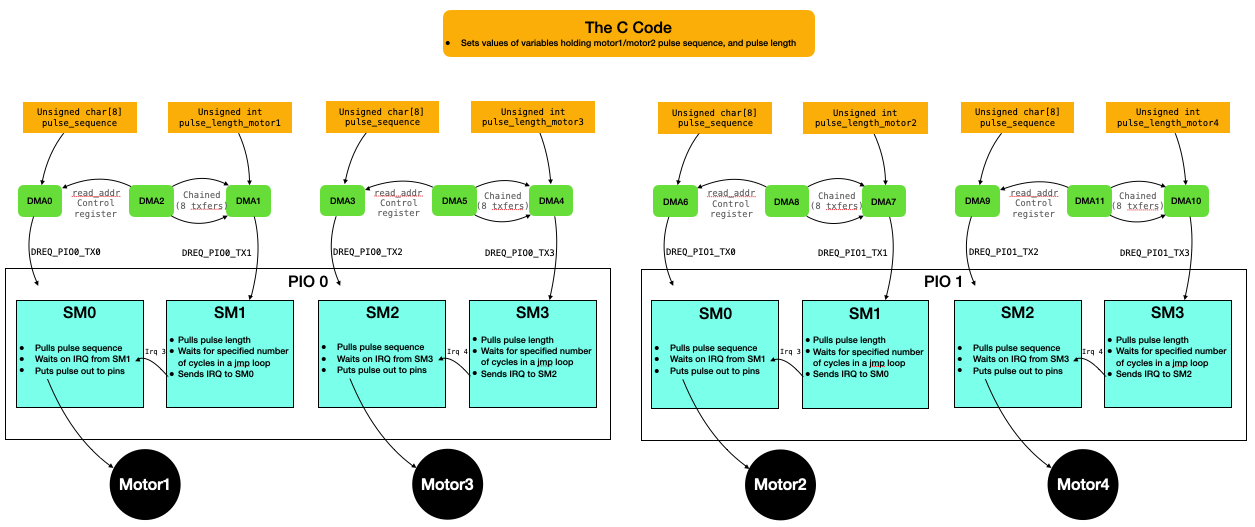
Pulse length state machine for speed control
The pulse length state machine is identical to that discussed previously, except that it does not wait for any signal from a step counting state machine.
out x, 32                     ; Shift value from OSR to scratch X (AUTOPULL ENGAGED)

countloop:
    jmp x-- countloop        ; Loop until X hits 0

irq 3                        ; Signal to send a pulse
Pulse generating state machine for speed control
Likewise for the pulse generating state machine
wait 1 irq 3            ; Wait for signal to put pulse on pins
out pins, 4             ; Put a pulse on the pins, AUTOPULL ENGAGED
Basic speed control demo
In the video below, four motors are being independently speed controlled via direct digital synthesis. Project zip.
Modification for position-only control
For other applications, only the position motor matters. That is, the user only cares about commanding the motor to move a certain number of steps in a particular direction, but doesn't care about the motor's speed (i.e., a fixed speed is acceptable). For such applications, we can eliminate the pulse length PIO state machine. This reduces the total number of state machines per motor to two, which allows for simultaneous control of 4 motors using all 8 state machines on both PIO cores. Driving these state machines requires all 12 DMA channels.
Step counting state machine for position control
Similar to before, allows for a step of length zero. Paced by irq 3 from the pulse generating state machine.
pull block                   ; Copy commanded # of steps from FIFO to OSR
mov x, osr                   ; Copy value from OSR to scratch X

countloop:
   jmp !x done              ; No pulse for zero steps
   irq wait 3               ; Signal for a step to occur, wait for flag to clear
   jmp x-- countloop        ; Loop until X hits 0

done:
   irq wait 1                  ; IRQ to CPU ISR, wait for CPU to clear
Pulse generating state machine for position control
Waits for a signal from the step counting state machine, then puts a pulse out onto the pins. Note that this state machine has been slowed down so as not to drive the motors too quickly.
wait 1 irq 3            ; Wait for signal to put pulse on pins
out pins, 4             ; Put a pulse on the pins, AUTOPULL ENGAGED
Slowing down the state machine:
// Note that max clock divider is 65536.
   sm_config_set_clkdiv(&c, 65000) ;
Basic position control demo
In the video below, four motors are being independently position controlled. Project zip
Examples
Some examples that use the driver described above.
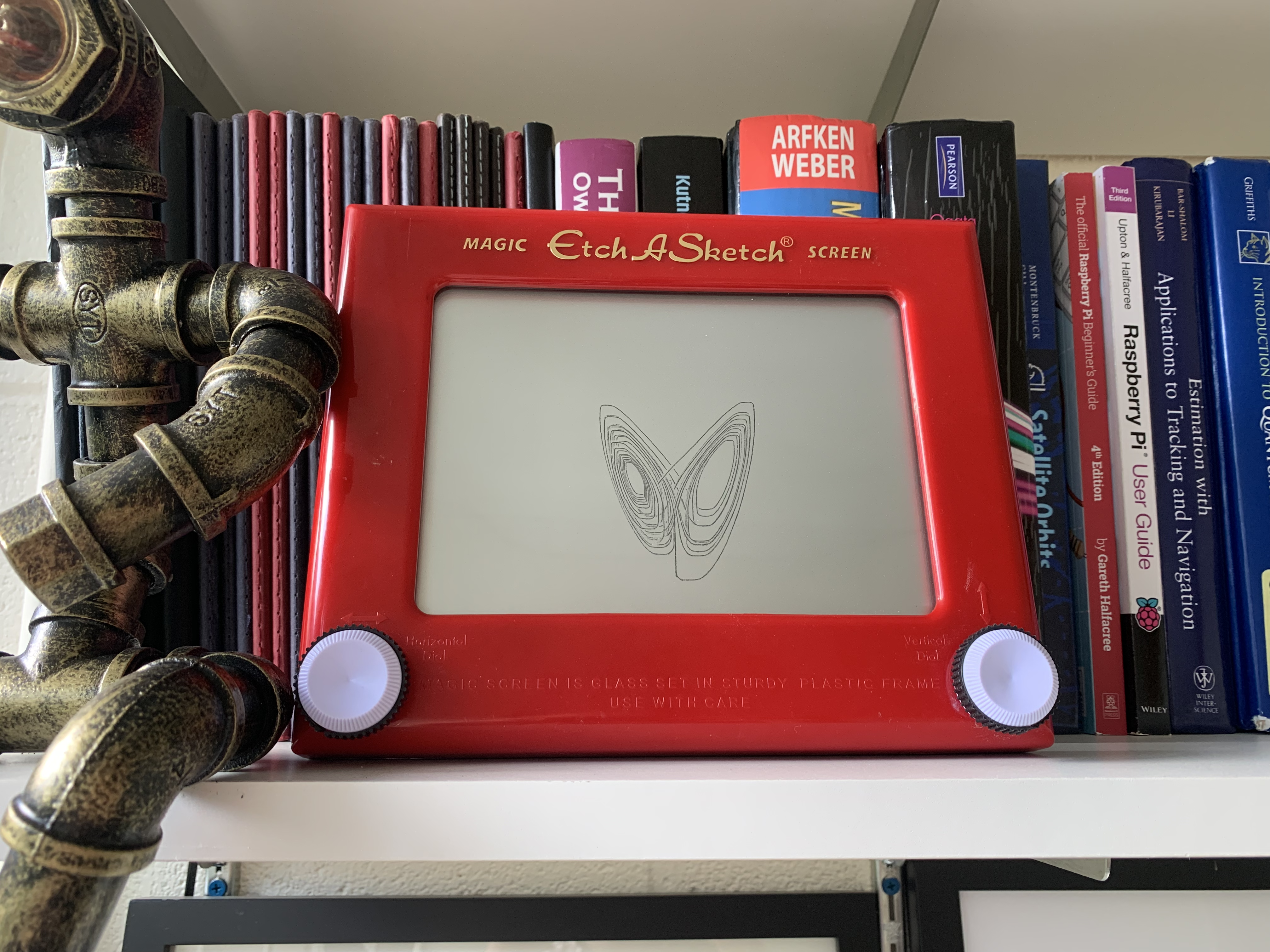
Strange Attractor
In this example, the Lorenz Equations are computed in a timer ISR. These equations are used to set the motor speed and direction for each motor, which is coupled via a geared belt to the knobs of an Etch-a-sketch. The trace on the etch a sketch thus represents the integral of these equations, yielding the famous Butterfly Curve. Project code.
DDS Circle Drawing
Direct Digital Synthesis is used to set the motor speeds. The speed of one motor is set to 90 degrees out of phase with the other, creating a circle. The motor has slightly square edges due to slop in the etch a sketch mechanism. Project code.
Delta Robot
Three stepper motors use position control to move the armatures of a delta robot. The armatures are made from wooden dowels. Compliant joints are formed with heatshrink, and rotating joints are formed by passing the dowels through coffee stirrers. The total materials cost for this device is approximately \$15. Project code
Nils Napp provided a 3D printed armature:
Comments and gotchas
Wait time is not velocity
A point that, in retrospect, should have been obvious. This cost me about half a day of debugging. Note that the velocity of the motor (in RPM, or similar units) is not directly proportional to the length of the pulse in cycles. It is inversely proportional! My DDS-generated circles were really weird and squared-off until I realized this.
Measure of distance: steps
Measure of time: interrupts
Measure of velocity: steps/interrupt
Interrupt rate: $F_s$ Hz
Cycles to interrupts: $\frac{125000000\text{ cycles}}{1\text{ sec}} \cdot \frac{1 \text{ sec}}{F_s \text{ interrupts}} = \frac{125000000}{F_s}$ cycles per interrupt
Fastest step: 125,000 cycles per step (experimentally determined)
Fastest speed: $\frac{1 \text{ step}}{125000 \text{ cycles}} \cdot \frac{125000000\text{ cycles}}{1\text{ sec}} \cdot \frac{1 \text{ sec}}{F_s \text{ interrupts}} = \frac{1000}{F_s}$ steps/interrupt
Slowest step: $\frac{125000000}{F_s}$ cycles per step
Slowest speed: 1 step/interrupt
Suppose that I have a target speed (steps per interrupt) and I want to convert that to a commanded cycles per step.
This gets encoded as the following:
// Interrupt frequency (Hz)
#define Fs 50.0

// Conversion from desired motor velocity (in steps/interrupt) to wait time
#define convert(a) (unsigned int)(125000000./(Fs*(float)a))
Same PIO state machines loaded on each PIO block
You can load an identical state machine onto each PIO block, or multiple times into different state machines in the same PIO block. Not mysterious, but this is the first I've experimented with that.
Maximum motor speed experimentally determined
To determine the maximum speed of the motor (the minimum number of cycles that each pulse could last and the motor would still turn), I simply reduced the value until the motor stopped turning.
If could reduce to 2 state machines, could have 4 motors or 2 motors + VGA
This driver is split into 3 state machines for each motor so that the user could, in the application, dynamically update the number of steps, speed, and direction of the motor. If an application did not require this much control (contant motor speed, for example), then one may be able to reduce the number of state machines to 2. If you did that, then you could fit the drivers for both motors on one PIO block. This could either allow you to control 4 motors simultaneously or use the other PIO block to do something like drive the VGA display.
Slop in the etch a sketch mechanism
It was quite difficult to make the etch a sketch draw a perfect circle because of slop in the mechanism. When the knob slows and reverses direction, it spins through a nonzero angle before the mechanism catches and starts moving the trace again. This small angle results in a flat edge on the circle. A solution is to have the motor pop quickly through a few steps when it reverses directions, but this is not entirely deterministic. Doing this made the circles look nicer, but it also made them slightly miss perfectly closing and retracing themselves.
GPIO's for PIO must be sequential
A simple datasheet point. If you are specifying the pins associated with an out instruction, then those GPIO pins are assumed to be sequential.
Autopulling is easy and worth it
Very easy to setup, saves an instruction.