PIO Assembly VGA Driver for RP2040 (Raspberry Pi Pico)
V. Hunter Adams
Project Code
Video explanation
The lecture below is all about this VGA library
Code organization
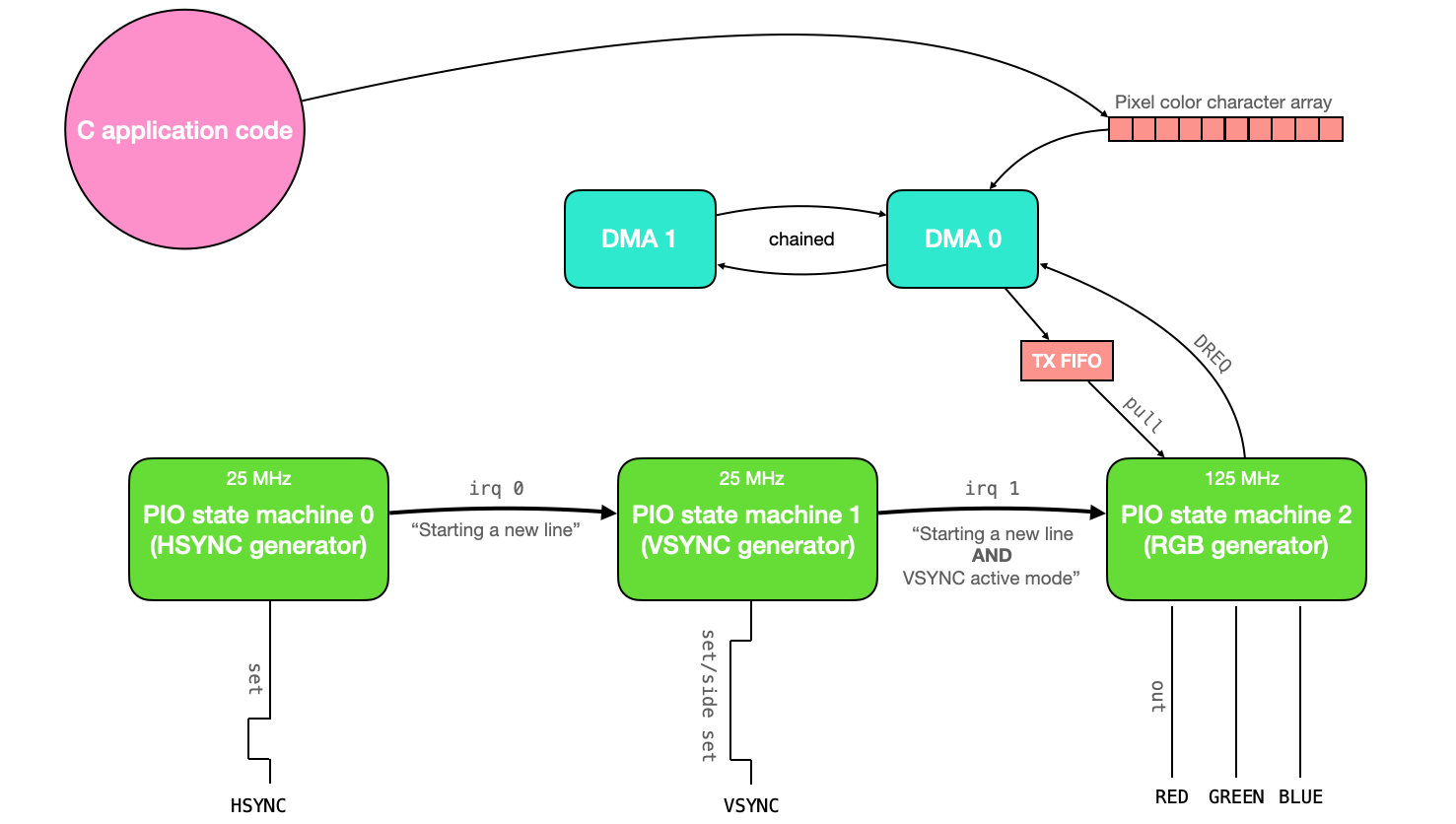
This code uses three PIO state machines (synchronized with one another via interrupts) to drive a VGA screen. The pixel data to draw on the screen is communicated to the PIO state machines through a DMA channel. All of this pixel data is stored in a global character array. So, in the application part of the code, the user need only modify the contents of that global character array and the changes will be automatically represented on the VGA screen.
In terms of resources, this code uses PIO state machines 0, 1, and 2 on PIO instance 0. It uses all 32 available PIO instructions, and it uses 2 DMA channels (one to communicate data to the PIO system, and the other to reconfigure and restart the first). Only 3 bits are used to store color data for each pixel, which means that there are only 8 colors which can be drawn to the screen. Because only 3 bits are used to represent the color in each pixel, each character in the character array stores the data for 2 pixels (and 2 of the 8 bits are wasted). This gives a total memory usage of 1.536 kBytes.
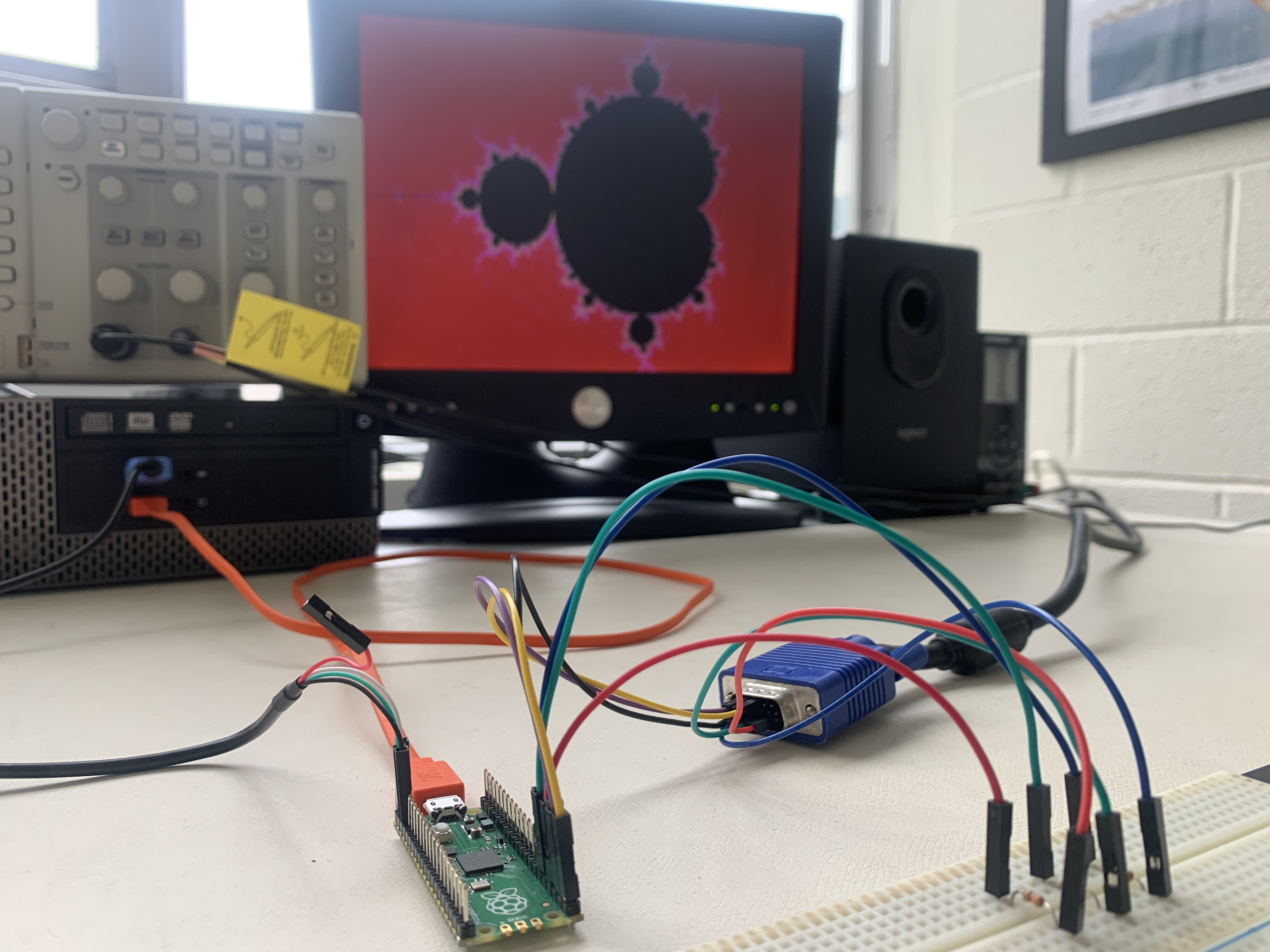
This document explains the VGA driver code, and then uses that VGA driver code to draw a Mandelbrot Set to the screen.
The VGA protocol
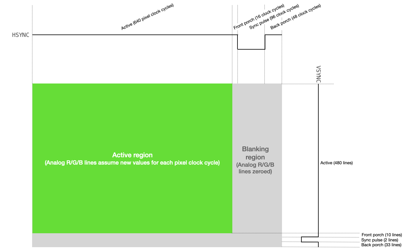
Driving a VGA screen requires manipulating two digital synchronization pins and three analog color pins (RED, GREEN, and BLUE). One of the synchronization pins, HSYNC, tells the screen when to move to a new row of pixels. The other synchronization pin, VSYNC, tells the screen when to start a new frame. The protocol is described below, both textually and visually.
- The VGA pixel clock runs at 25.172 MHz (on my VGA screen, I can get away with 25 MHz)
- Both
HSYNCandVSYNCstart in active mode (logic level high) HSYNCremains in active mode for 640 pixel clock cycles (i.e., one row of the VGA display).- For each of the 640 clock cycles, the voltages on the
RED,GREEN, andBLUElines are varied between 0 and 0.7V, with each voltage representing the intensity of that particular color for a particular pixel. - After 640 clock cycles, the
RED,GREEN, andBLUElines are set to 0, and theHSYNCline remains high thru its frontporch (16 pixel clock cycles). HSYNCis set to logic-level low for 96 pixel clock cycles (this is the horizontal sync pulse)HSYNCis set to logic-level high thru its backporch (48 pixel clock cycles).HSYNCthen returns to the start of active mode (step 2, above), and the process is repeated for the next row of pixels. Each row of pixels is a line.VSYNCremains in active mode (logic level high) for 480 lines.- After 480 lines, the voltages on the
RED,GREEN, andBLUElines are set to 0, and theVSYNCline remains high thru its frontporch (10 lines). VSYNCis set to logic-level low for 2 lines (this is the vertical sync pulse).VSYNCis set to logic-level high thru its backporch (33 lines).VSYNCthen returns to the start of active mode (step 2, above), and the process is repeated for the next frame.
Generating Hsync
The PIO assembly code below generates the HSYNC for the VGA display. Note that this code is clock divided to execute at 25MHz.
pull block              ; Pull from FIFO to OSR (only happens once)
.wrap_target            ; Program wraps to here

; ACTIVE + FRONTPORCH
mov x, osr              ; Copy value from OSR to x scratch register
activeporch:
   jmp x-- activeporch  ; Remain high in active mode and front porch

; SYNC PULSE
pulse:
    set pins, 0 [31]    ; Low for hsync pulse (32 cycles)
    set pins, 0 [31]    ; Low for hsync pulse (64 cycles)
    set pins, 0 [31]    ; Low for hsync pulse (96 cycles)

; BACKPORCH
backporch:
    set pins, 1 [31]    ; High for back porch (32 cycles)
    set pins, 1 [12]    ; High for back porch (45 cycles)
    irq 0       [1]     ; Set IRQ to signal end of line (47 cycles)
.wrap
Line by line, this is what happens:
pull blockwaits for the C code to put information into the pio state machine's TX buffer, and then pulls that information into the output shift register. Because this line of code is above thewrap_targetdirective, it will only be executed once. This is used to store the length of the active+front porch modes of theHSYNCsignal (640+16) in the output shift register. We must initialize this value in this way because we cannot set the value of any register in PIO assembler to any number greater than 31.- The
.wrap_targetdirective indicates the location to which the code will wrap once it has completed. If we didn't have the.wrap/.wrap_targetdirectives, the code would wrap back to its first line. - We then enter active/front porch modes. The next line of code moves the data from the output shift register (which contains the length of the active + frontporch modes) to the scratch register
x. activeporchis a label which we can use with ajmpinstruction to return to a specific location in the code.jmp x-- activeporchwill decrement the value in the scratch registerxand return to theactiveporchlocation in code for as long as the value ofxis greater than 0. Whenxequals 0, thejmpcondition fails and the code moves on to the next line.- The
pulselabel specifies the sync pulse part of theHSYNCsignal. - We set the value of group
pins(mapped separately to specific GPIO ports) low, and wait for 31 cycles. Note that the delay starts after the line is executed. So, this line will set the pins value low, then wait for 31 additional cycles for a total of 32. - We do this again (to bring the total time with pins low to 64 cycles)
- And again, to bring the total time with pins low to 96 cycles (the length of the sync pulse)
- We then enter the backporch. The pins are set high, and we delay for 31 cycles.
- Pins remain high, and we delay for 12 additional cycles.
- We set interrupt 0 (this is used to synchronize with the
VSYNCassembly code), and we delay for 1 cycle. This delay is here so that this code returns to active mode in the same cycle as theVSYNCassembly code with which it is synchronized.
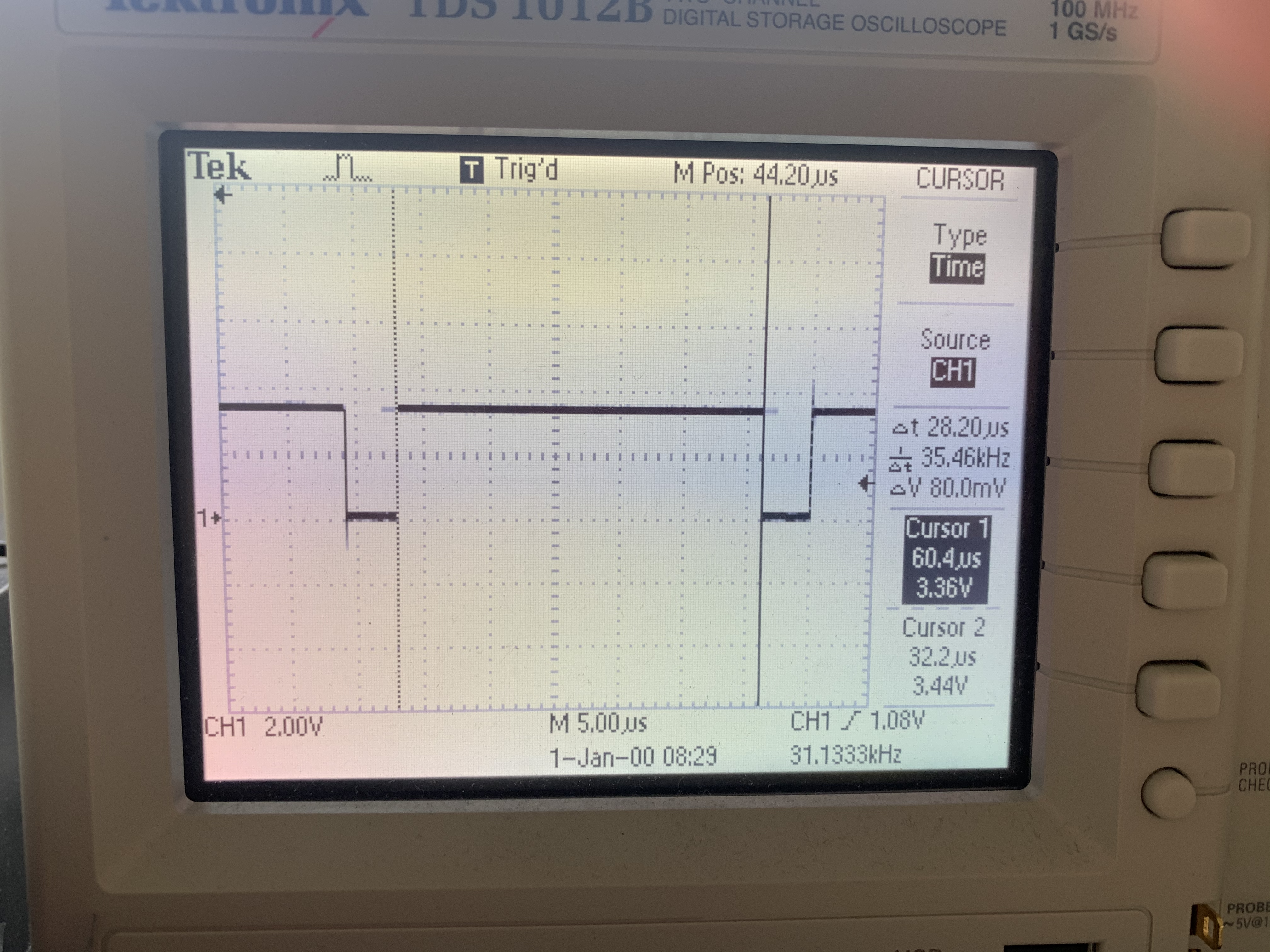
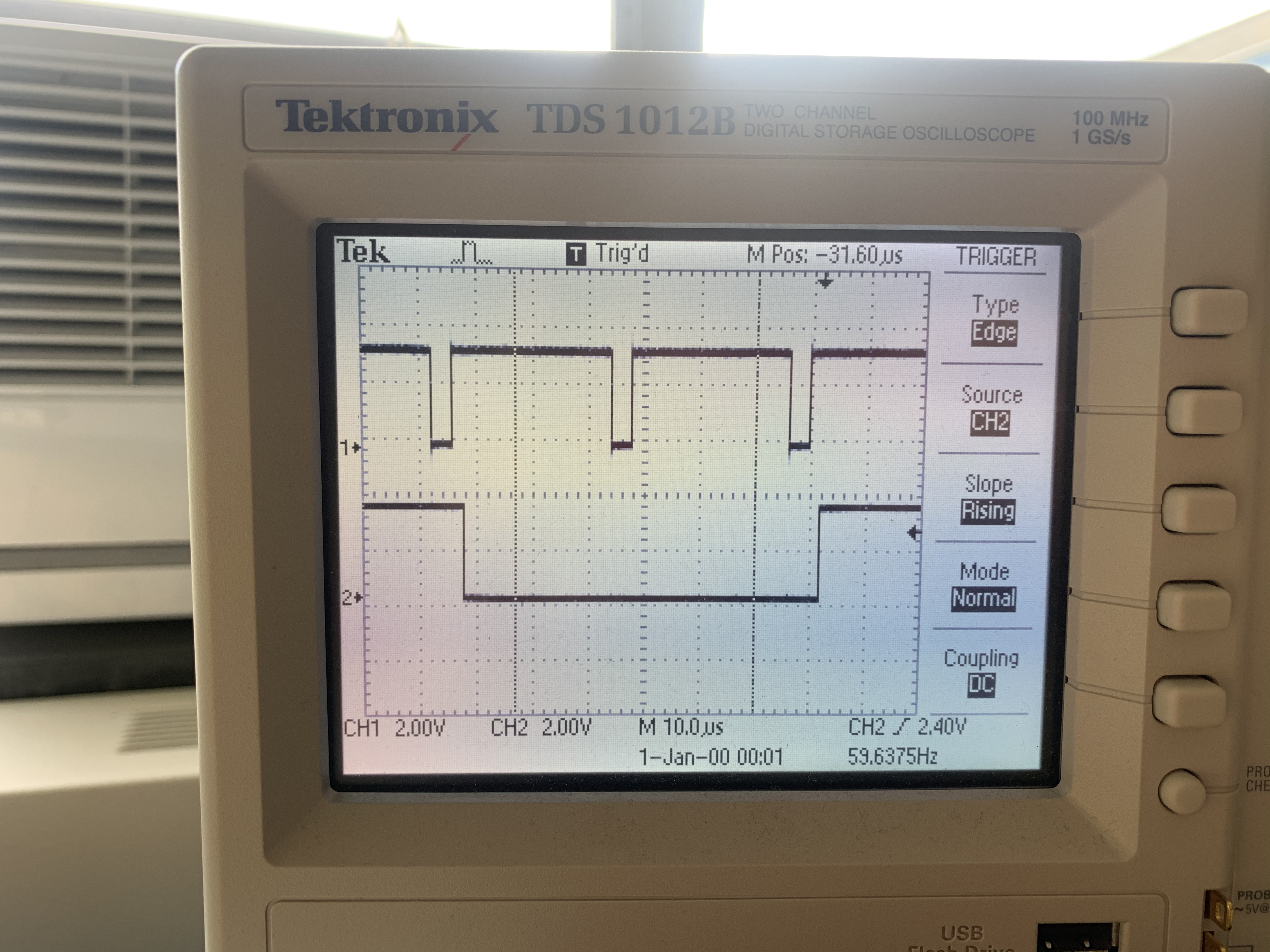
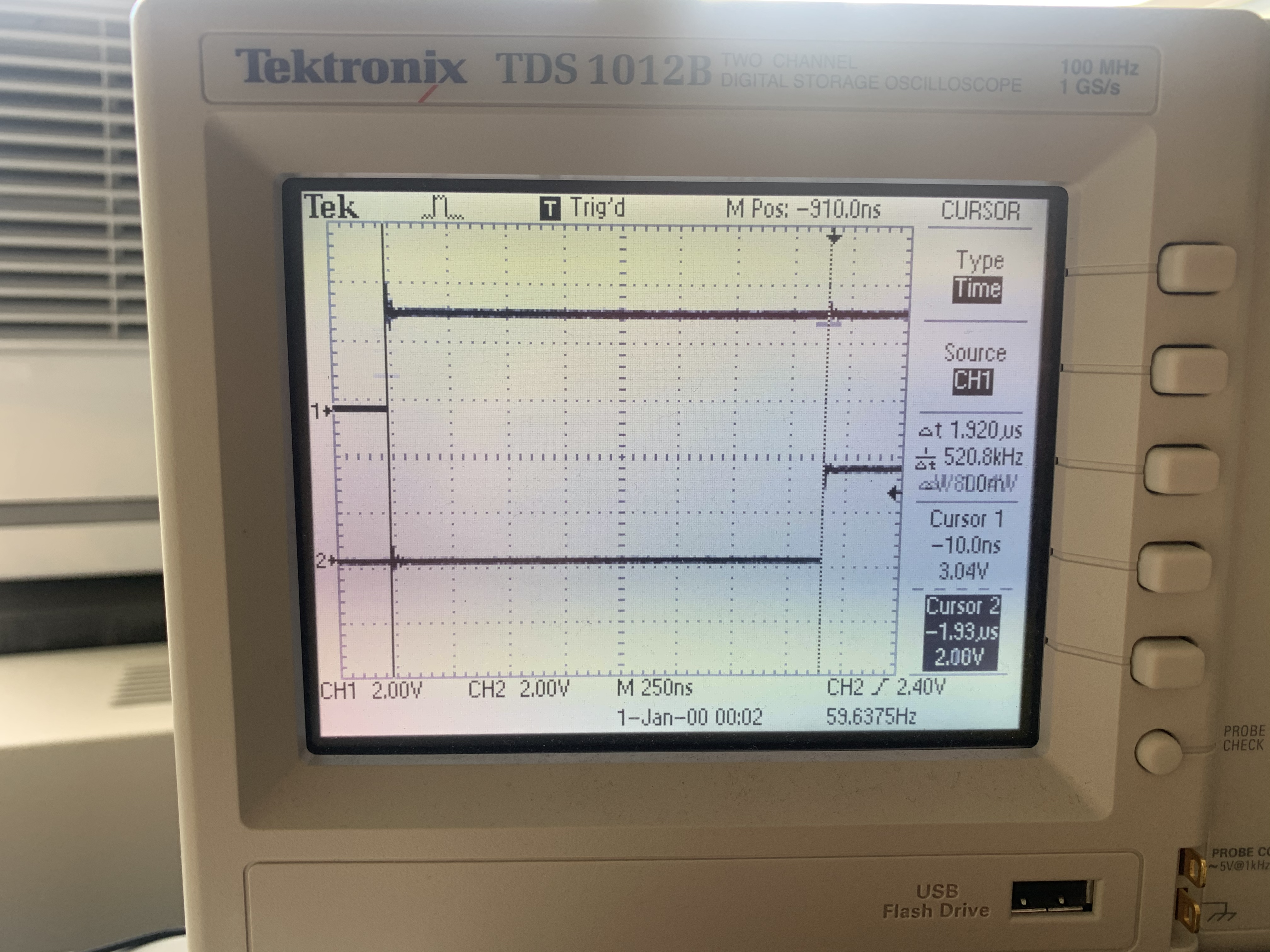
Here is what this looks like on the scope:
Generating Vsync
The following code generates VSYNC. This state machine is also clock-divided to 25MHz, but it is largely paced by the HSYNC state machine (since VSYNC operates in units of lines and not pixel clock cycles).
pull block                        ; Pull from FIFO to OSR (only once)
.wrap_target                      ; Program wraps to here

; ACTIVE
mov x, osr                        ; Copy value from OSR to x scratch register
active:
    wait 1 irq 0                  ; Wait for hsync to go high
    irq 1                         ; Signal that we're in active mode
    jmp x-- active                ; Remain in active mode, decrementing counter

; FRONTPORCH
set y, 9                          ; Use y scratch register as counter
frontporch:
    wait 1 irq 0                  ; Wait for hsync to go high
    jmp y-- frontporch            ; Remain in frontporch, decrementing counter

; SYNC PULSE
set pins, 0                       ; Set pin low
wait 1 irq 0                      ; Wait for one line
wait 1 irq 0                      ; Wait for a second line

; BACKPORCH
set y, 31                         ; First part of back porch into y scratch register (and delays a cycle)
backporch:
    wait 1 irq 0   side 1         ; Wait for hsync to go high - SIDESET REPLACEMENT HERE
    jmp y-- backporch             ; Remain in backporch, decrementing counter

.wrap                             ; Program wraps from here
Line by line, this is what happens:
pull blockwaits for the C code to put information into the pio state machine's TX buffer, and then pulls that information into the output shift register. Because this line of code is above thewrap_targetdirective, it will only be executed once. This is used to store the length of the active mode of theVSYNCsignal (480 lines) in the output shift register. We must initialize this value in this way because we cannot set the value of any register in PIO assembler to any number greater than 31.- The
.wrap_targetdirective indicates the location to which the code will wrap once it has completed. If we didn't have the.wrap/.wrap_targetdirectives, the code would wrap back to its first line. - We then enter active mode. The next line of code moves the data from the output shift register (which contains the length of the active mode) to the scratch register
x. activeis a label which we can use with ajmpinstruction to return to a specific location in the code.- The state machine wait for the interrupt that is set by the
HSYNCstate machine, signalling the end of a line. These interrupts are how theVSYNCmachine paces itself and counts off lines. - Every time that a new horizontal line is signalled by the
HSYNCstate machine and theVSYNCstate machine is in active mode, it sets a separate interrupt. This interrupt is used by the RGB PIO machine to know when to start putting data on the RGB pins. jmp x-- activewill decrement the value in the scratch registerxand return to theactivelocation in code for as long as the value ofxis greater than 0. Whenxequals 0, thejmpcondition fails and the code moves on to the next line.- The next line sets the value of the scratch register
yto the length of theVSYNCfront porch (minus 1 to get 10 total waits). - The
frontporchlabel specifies the front porch part of theVSYNCsignal. - As before, the code uses
waitandjmpcommands to remain in this state until theHSYNCstate machine sets the interrupt for the correct number of times. - We set the value of group
pins(mapped separately to specific GPIO ports) low, and then wait for twoHSYNClines to complete. This is the length of theVSYNCsync pulse. - We then enter the backporch. The length of the backporch is stored in scratch register
y. - As before, we use the
waitandjmpcommands to remain in this state for the appropriate number of lines. NOTE: We use the side set instruction to set theVSYNCline high instead of a set instruction. The set and side set pins are configured to overlap, and this saves us one instruction.
Generating RGB signals
The state machine for generating the 25MHz RGB signals is comparatively simple. After some intialization of counting registers, it zeroes the color pins until it receives the signal from the VSYNC state machine that a newline has been started and VSYNC is in active mode. When this condition is met, the RGB machine knows that it should clock out 640 pixels (i.e., one row). It does so by doing a pull from the TX FIFO (which is being fed pixel data from a DMA channel), putting the first 3 bits out to the RGB pins, waiting the appropriate number of cycles, putting the next 3 bits out, waiting the appropriate number of cycles, then jumping back and doing it again until it completes the row. Once the row is complete, it zeroes the outputs and waits again for the signal from the VSYNC machine. Note that this state machine runs at 125 MHz.
pull block                  ; Pull from FIFO to OSR (only once)
mov y, osr                  ; Copy value from OSR to y scratch register
.wrap_target

set pins, 0                   ; Zero RGB pins in blanking
mov x, y                      ; Initialize counter variable

wait 1 irq 1 [3]            ; Wait for vsync active mode (starts 5 cycles after execution)

colorout:
    pull block              ; Pull color value
    out pins, 3 [4]         ; Push out to pins (first pixel)
    out pins, 3 [2]         ; Push out to pins (next pixel)
    jmp x-- colorout        ; Stay here thru horizontal active mode

.wrap
Using DMA to communicate pixel data
There exists a global character array called vga_data_array which is of length TXCOUNT (153600). Each character in this array contains the color information for two adjacent pixels. This color information is communicated, 8 bits at a time, to the RGB PIO state machine via a DMA channel. That DMA channel is paced by the DREQ_PIO0_TX2 data request signal (so that it only transfers when the PIO machine has emptied the FIFO), and it is restarted and reconfigured by a second DMA channel which is chained to the first. This second DMA channel writes a pointer to the start address of the first DMA channel to its read_address register.
// DMA channels - 0 sends color data, 1 reconfigures and restarts 0
    int rgb_chan_0 = 0;
    int rgb_chan_1 = 1;

    // Channel Zero (sends color data to PIO VGA machine)
    dma_channel_config c0 = dma_channel_get_default_config(rgb_chan_0);  // default configs
    channel_config_set_transfer_data_size(&c0, DMA_SIZE_8);              // 8-bit txfers
    channel_config_set_read_increment(&c0, true);                        // yes read incrementing
    channel_config_set_write_increment(&c0, false);                      // no write incrementing
    channel_config_set_dreq(&c0, DREQ_PIO0_TX2) ;                        // DREQ_PIO0_TX2 pacing (FIFO)
    channel_config_set_chain_to(&c0, rgb_chan_1);                        // chain to other channel

    dma_channel_configure(
        rgb_chan_0,                 // Channel to be configured
        &c0,                        // The configuration we just created
        &pio->txf[rgb_sm],          // write address (RGB PIO TX FIFO)
        &vga_data_array,            // The initial read address (pixel color array)
        TXCOUNT,                    // Number of transfers; in this case each is 1 byte.
        false                       // Don't start immediately.
    );

    // Channel One (reconfigures the first channel)
    dma_channel_config c1 = dma_channel_get_default_config(rgb_chan_1);   // default configs
    channel_config_set_transfer_data_size(&c1, DMA_SIZE_32);              // 32-bit txfers
    channel_config_set_read_increment(&c1, false);                        // no read incrementing
    channel_config_set_write_increment(&c1, false);                       // no write incrementing
    channel_config_set_chain_to(&c1, rgb_chan_0);                         // chain to other channel

    dma_channel_configure(
        rgb_chan_1,                         // Channel to be configured
        &c1,                                // The configuration we just created
        &dma_hw->ch[rgb_chan_0].read_addr,  // Write address (channel 0 read address)
        &address_pointer,                   // Read address (POINTER TO AN ADDRESS)
        1,                                  // Number of transfers, in this case each is 4 byte
        false                               // Don't start immediately.
    );
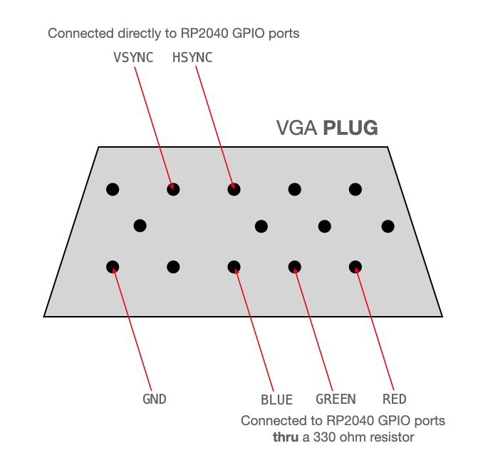
Attaching hardware
Both of the synchronization lines (HSYNC and VSYNC) are connected directly from the GPIO ports of the RP2040 to the appropriate pins on the VGA connector (labeled below). The R/G/B color pins are analog, and the display expects a voltage in the range of 0-0.7V. The output from the RP2040 is 3.3V. Within the display, there is a 70 ohm resistor to ground. So, putting a 330ohm resistor between the GPIO ports and the VGA connector creates a voltage divider that keeps the output voltage within a safe range for the display.
Demonstrations
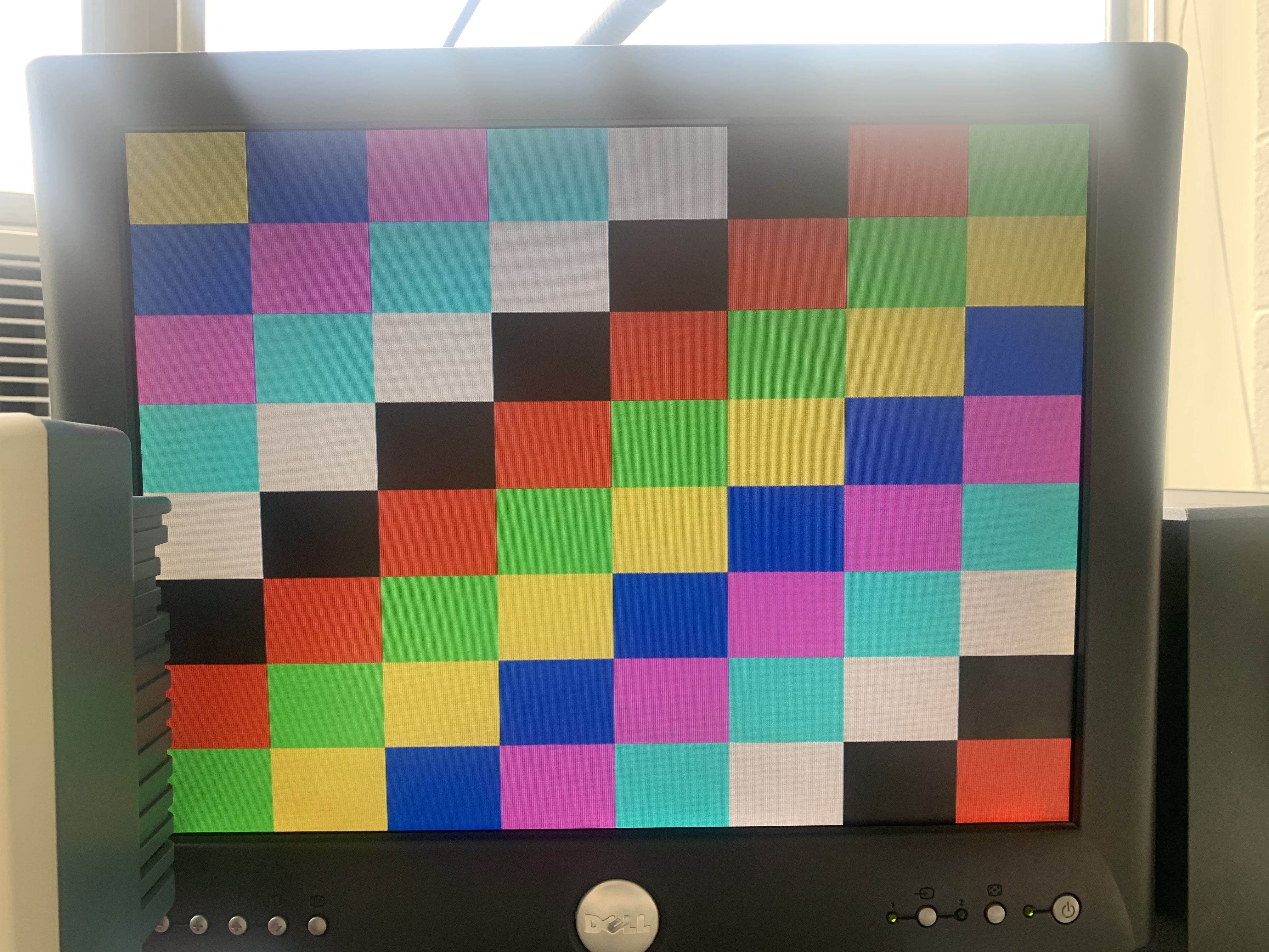
Checkerboard
The first test was to draw a checkerboard that included all 8 possible colors. This confirmed that the HSYNC/VSYNC lines were stable (no quivering of the checkerboard edges) and it confirmed that the color information in the color array was being interpreted and communicated correctly. Project Zip.
Mandelbrot Set
The theory behind the Mandelbrot Set is covered on others of my project pages, so it isn't covered here. As a second demonstration, the RP2040 computes and renders the Mandelbrot Set. One a single core, it completed 79747133 complex iterations (fixed point) in 86.845272 sec. Project Zip.
Multicore acceleration of Mandelbrot Set
Core 0 is used to calculate the top half of the Mandelbrot Set, from left-to-right. Core 1 is used to calculate the bottom half from right-to-left. This nearly halves the total compute time to 46.458416 sec. Project Zip.
The Barnsley Fern
Computes 100,000 points in the Barnsley Fern in 308.494 ms. Project Zip.
Conway's Game of Life
The video below shows the RP2040 running Conway's Game of Life. Each cell is 2x2 pixels, and the computation+rendering runs at just over 15 frames/second. Project Zip.
Graphics primitives
I recommend using this project as the starting point for graphics projects. This separates all of the VGA configuration and control into a header file and provides a library of graphics functions (line drawing, text, rectangles, circles, etc.). This is a translation of the library that we've been using with the PIC32 microcontroller. Download here.
Gotchas
- The Hsync and Vsync PIO state machines should be started simultaneously. Because the RGB state machine is running at full speed, synchronization with the other two is not required.
- The DMA read address trigger requires a pointer to the address of the start of the color array, not the address itself (this bug took a while to track down)
- When attempting to read high-speed signals on the scope, note that there is some capacitance in the clip lead and some inductance in the grounding alligator cable. This capacitance/inductance can produce some ringing. To attenuate this ringing, remove the clip lead and grounding cable, retune the probe in this configuration, and ground the lead using a short length of wire. This reduces ringing considerably.
- The read_addr register for DMA channel 0 expects a pointer to the address of the start of the pixel array, not the address itself.