Video discussion of the content on this page
Hardware Hookup
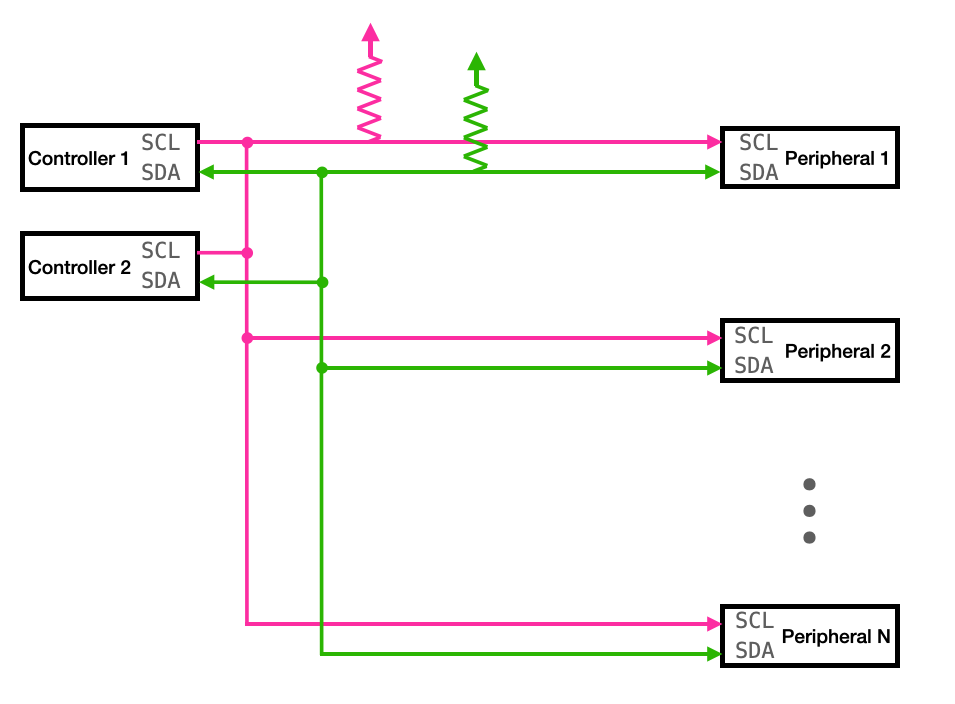
There are only two lines which connect a controller (or main) and a peripheral (or secondary) device. One of these is a clock line, and the other is a data line. This suggests that data can only be moving in one direction at a time, and indeed that is the case. Because we have all the controllers and peripherals talking over the same data line, the protocol must be careful about who is talking to whom, and who is allowed to manipulate each of these lines at a given moment.
You’ll notice that each of these lines has a pull-up resistor, the precise value for which depends on the number of peripherals on the bus. For a single peripheral, something like 4.5k is a good place to start. This pull-up resistors ensure that both lines are high when the bus is idle. That is to say, when nobody is communicating with anybody, both SCL and SDA are sitting at VCC.
Timing Diagram
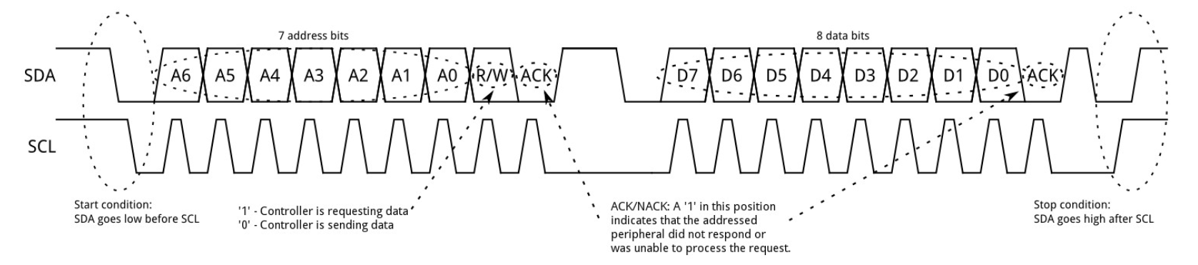
The timing diagram below comes from SparkFun. Let us walk through it.
Start condition
You can see that, before the transmission begins, both the data and clock lines are at an idle high state. To signal the start of a transmission, one of the controllers will pull the data line low while the clock line stays high. That - data low while clock high - is the signal for a start. If two controllers try to start a transmission at the same time, whichever is the first to pull that data line low will gain control of the bus. While one controller is in control of the bus, no other controllers can control the bus. The bus is released after a stop condition, which we’ll discuss in a second.
Addressing
After the start condition, there will be 9 clock pulses. The data line is valid when the clock is high, as you can see, and the value on the line changes when the clock is low. It is the controller that is generating these clock pulses. The first 7 bits shifted out onto the data line are the address of the peripheral with which the controller would like to communicate. These come out MSB first.
Sidenote on addresses
By the way, a 7-bit address suggests that you could put 128 peripherals on this bus. And, indeed (in principle) you could. In practice, for reasons that are a little annoying, this is probably not possible.
It is almost always the case that the address of a peripheral is set, in hardware, by the manufacturer. In other words, for many peripherals, you don’t set the address, you look up the address in the data sheet. What value do you think most manufacturers choose for their devices? Yeah, 0, or 1, or some low number.
So in reality, you’ll probably not be able to put as many devices on the bus as you’d otherwise be able to if you could configure the full address. Some manufacturers make only a few of these bits configurable so that you could use a handful of their devices together, but it’s very rare to have total configurability. Annoying, but that’s the way it is.
Read/write bit
On the 8th clock pulse, the controller tells the peripheral whether it would like to read or write. A 1 means that the controller is requesting data from the peripheral. A 0 means that the controller is sending data to the peripheral (perhaps configuration settings).
Acknowledgement bit
On the 9th clock bit, the peripheral takes control of the data line. It will pull the data line low to indicate that it has understood, and a 1 will be in this position to indicate that the addressed peripheral did not respond to or understand the request.
Data and Ack
The controller then keeps the data line low, until it sends out 9 more bits. The first 8 of these bits are data, and the 9th is an ACK. As before, the peripheral pulls this low to acknowledge receipt, and lets it high if it hasn’t understood. This data frame may come from the controller or it may come from the peripheral, but the controller is manipulating the clock.
There may be more than 1 of these data frames. The controller will continue generating clock pulses at a regular interval, and the data will be placed on SDA by either the controller or the peripheral depending on whether the R/W bit indicated a read or write operations. The number of these data frames is arbitrary.
Stop condition
Once all of the data frames are complete, the controller will generate a stop condition. A stop is indicated by a low to high transition of the SDA line after a low to high transmission of the SCL line, and with the SCL line remaining high. During normal data writing, the value on the SDA line does not change when SCL is high. This only happens during the stop condition. That can setup some potential bugs, since it’s not an error, it’s a valid stop condition.
Clock stretching
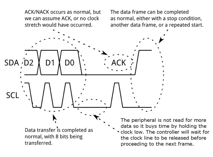
Previously, I suggested that the controller is in control of the clock line and peripherals simply put data on the bus or take data off the bus in response to the controller’s pulses. Sometimes, however, the controller moves too quickly for the peripheral. Perhaps some previous operation hasn’t yet been completed, or perhaps an analog to digital conversion hasn’t yet finished. In this case, some peripheral devices will hold the clock line low. The controller is unable to send additional clock pulses until the clock is released by the peripheral, and so the peripheral can buy itself some time. This is illustrated here, where you can see the peripheral delays the pulse associated with the ack bit.
Repeat start conditions
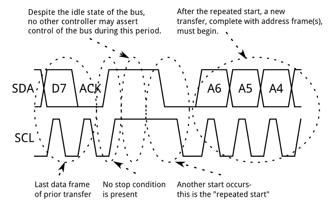
It is sometimes the case that a controller must exchange a few messages without giving any other controllers the opportunity to seize the bus. A controller can do this with a repeated start condition.
Recall that a stop condition is given by a low to high transition of SDA after a low to high transition of SCL with SCL held high, and a start condition is given by a data low while clock high. If a controller does what is shown here, then it can send a second start condition without having ever sent a stop condition, which would signal to other controllers that the bus is available.
After the ACK, it holds SCL low while SDA goes high. This puts both SDA and SCL into a high state without ever having passed through a stop condition. From this state, a start condition can be sent and the whole process can repeat. In this way, a controller can do a bunch of transactions without ever yielding the bus.
10-bit Addressing
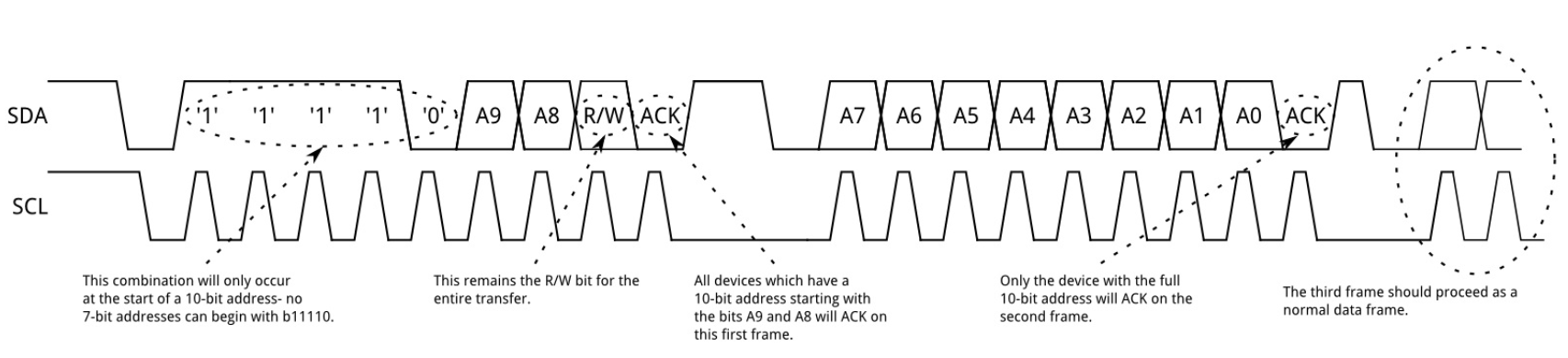
10-bit addressing is a method by which the number of bits in peripheral addresses can be increased from 7 to 10 which, in principle, lets you put more devices onto the bus.
The controller sends a start condition, and then 9 clock pulses as before. The data associated with the first 4 of these pulses is 1, followed by a 0, followed by the top 2 most significant bits of the 10-bit peripheral address and a R/W bit. All peripherals with a match in the first two bits of their address will then assert the ACK together. In the next transfer, the controller transmits the bottom 7 bits of the peripheral address. This time, only the peripheral that matches all 10 bits will assert the ACK.
7 bit devices and 10 bit devices can exist on the same bus, since the leading ‘11110’ part of the address is not a part of any valid 7-bit address.
Pros and Cons
Generally speaking, if a particular protocol exists it’s because it fills some niche in the application space of projects. There are circumstances in which SPI is really nice, circumstances in which UART is nice, and circumstances in which I2C is nice. Sometimes, your choice of protocol will be enforced by the manufacturer of the device that you’d like to use. If that sensor only uses I2C, you’re gonna use I2C. But, if you have some flexibility in your design, you might choose one over the other. Why might you choose I2C, and why might you not?
Pros
One of the obvious pros of i2c is illustrated on the hardware connections diagram. There’s only 2 lines, and they’re shared among all controllers and all peripherals! From an I/O utilization standpoint, that’s incredibly efficient.
One of the other practical benefits is that you can see everything that’s happening with a 2-channel scope. The protocol is a bit annoying, as compared to something like SPI, but you can see the whole bus with 2 channels. That’s kinda nice.
This protocol is also pretty easy to bit bang, if you need to. If you look online, there are lots of implementations for bit-banged i2c controllers.
And, finally, 7-bit addressing means that you can put a ton of devices on this bus. Though, as I already mentioned, that’s probably not actually possible, given that these addresses are often immutable (or nearly immutable) and set by the device manufacturer.
Cons
Why not use I2C? Well, the annoying protocol can make debugging a pain, more of a pain than something like SPI. But the big CON is SPEED. The baud rate is usually lower than 400 KHz, and the protocol drops the effective baud rate lower than that (since you have to do addressing, acks, r/w, etc.). You could crank the SPI channel on the PIC32 up to 20 MHz if you really wanted to.
An Example Datasheet
In all the timing diagrams, the controller and peripheral send “data” to one another. A good question is . . . what data? This is often the hardest part about working with a new peripheral, because the answer to that question is different for each. For each, there may be certain bit patterns for configurations, others to read this or that register or to gather a measurement of some variety. You need to read the data sheet to determine what data you need to send from a controller in order to get the data that you want from the peripheral, and to determine the representation of the data that you receive from that peripheral. Consider the Si-7021 as an example.
The Si7021
We’ll use the Si7021 temperature and humidity sensor as an example. Why? Sort of arbitrarily, but also because it has a variety of configurations that make it a good representative example. Let’s open up the data sheet, and if we scroll down to page 18, we’ll find the documentation on the I2C interface.
Si7021 Address and Command Table
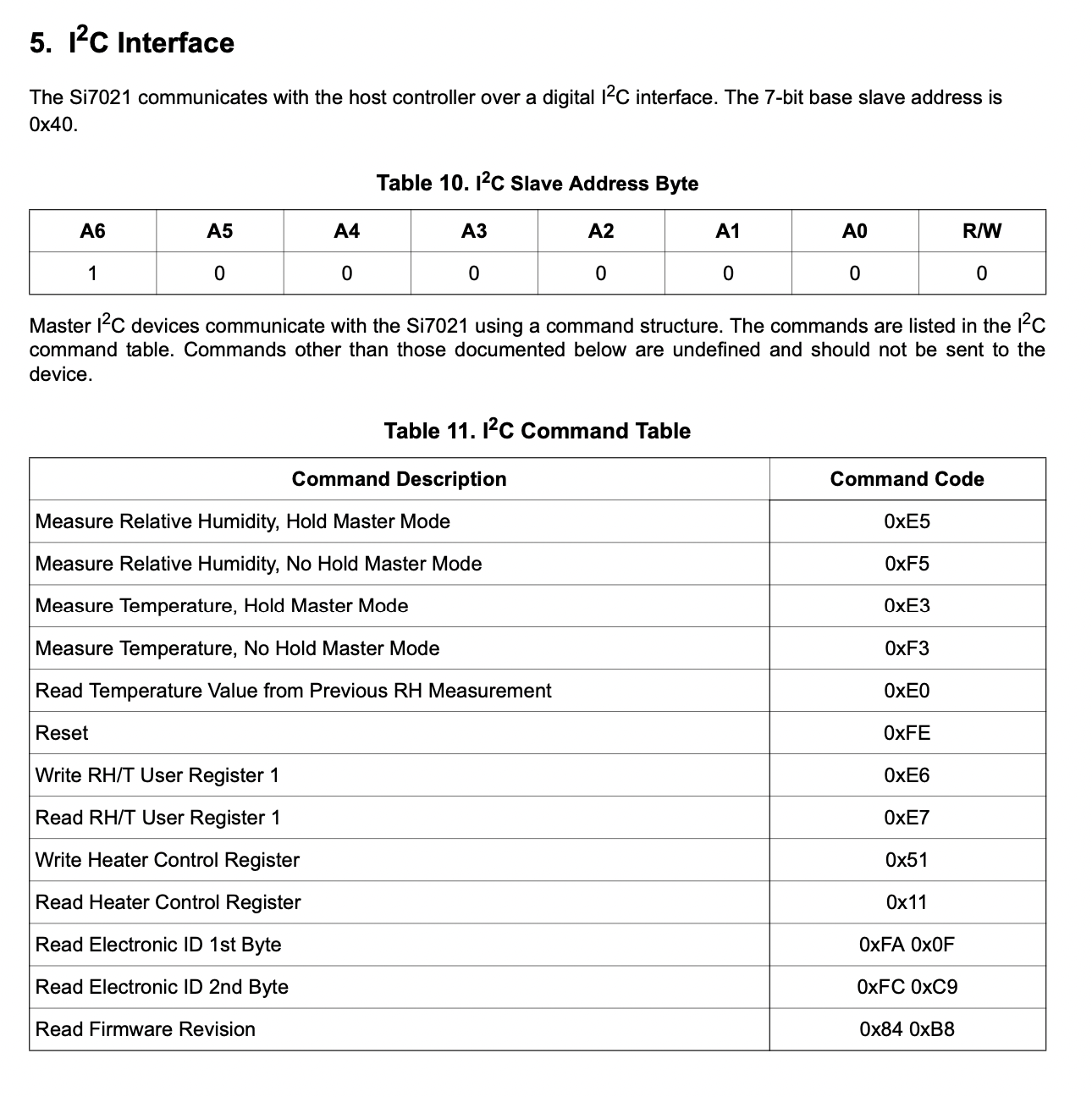
The first thing that we find in this section is the following sentence: “The Si7021 communicates with the host controller over a digital I2C interface. The 7-bit slave address is 0x40.” So, there you go. You can’t change that, the address is 0x40 and you have to deal with it. Frustratingly, this means that you can only put one of these devices on a bus. But, this is exactly what I was talking about earlier.
Directly underneath that you can see a set of command codes. We’ll need to read a bit farther to learn how to use these command codes, but this tells us all of the stuff that we can ask of this device through the I2C interface. We can ask for relative humidity and temperature measurements in 2 different modes (what are those modes? Not sure yet, we’ll find out). We can reset the device. We can read and write two control registers, one of which controls the relative humidity and temperature sensor configurations and the other of which controls an onboard heater. And, finally, we can read the values in some read-only registers that tell us about the device ID and the firmware revision.
So, in short, we can ask for a few different measurements, ask for a reset, and read/write a few different registers, some of which control configurations and others of which have read-only information. How do we actually do that?
Issuing a measurement command
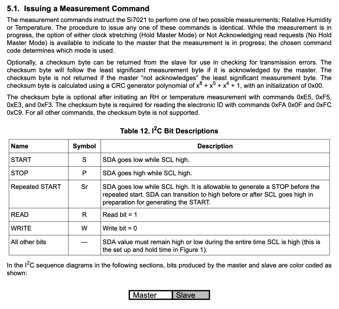
How do we issue a humidity or temperature measurement command? In these paragraphs, it is explained that you can ask for these measurements in one of two ways. When you ask for a measurement, it is not immediately available to return. It takes some time. You can either setup the device in Master Hold Mode, in which the peripheral clock stretches until the measurement is complete, or in No Hold Master Mode. In NHMM, the device does not return the ACK bit. You would then have the master keep requesting the measurement until it gets the ack. Let’s look at this visually. In order to understand the diagrams on the next page, we need to look at this.
We see that they are going to use S for start, P for stop, Sr for repeated start, R for read, and W for write. Furthermore, data from the master will be white, and data from the slave will be gray.
Let’s look first at Hold Master Mode.
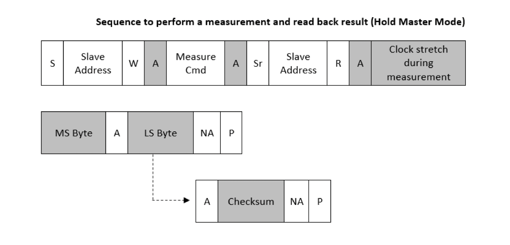
You can see that the master first issues the start bit. It then sends the slave command (fixed at 0x40) and sets the write bit to tell the device that it’s going to send it information. The device will send an ACK. Then the master sends the measure command, as listed in the table above, and the slave responds with an ACK. The master will to a repeated start and send out the address again, followed by a read command. So, at this point, it is trying to get the measurement (2 bytes) from the slave. As we said, these aren’t ready right away. In HMM, the slave clock-stretches (holds the clock low) and then sends the MS byte, to which the master acks, followed by the LS byte, to which the master Nacks and then ends the transmission. Optionally, you can configure the slave to also send a checksum after the LSB to verify that everything was received ok.
In NHMM, the beginning looks exactly the same, except the slave doesn’t clock stretch. Instead, it indicates thru the NACK that the data is not ready. So, the master does a repeated start and asks again. It will keep doing so until it gets the ACK followed by the data, as before.

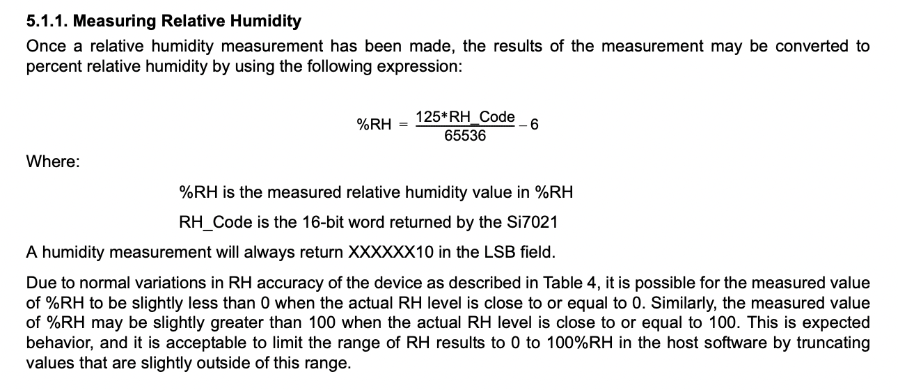
Unit conversion
On the next page, we are told how to convert the received measurement into units that we care about. This is followed by a similar diagram from above that tells us how we measure temperature value from previous RH measurement. This is stored in an onboard register, so it is ready to go when we ask (assuming that we’ve made a humidity measurement). Since the measurement is not actually performed, we get that value back right away.
The next page then shows us how to convert that to Celsius.
Reading and writing registers
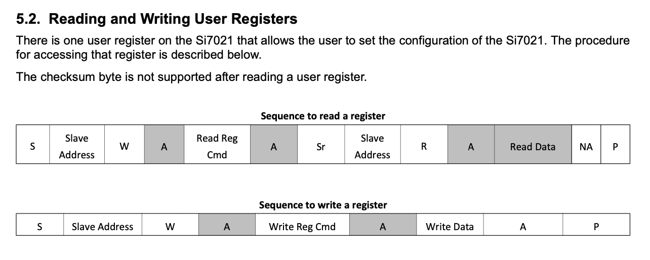
On the next page, we are told the sequence that is required to read and write registers. To read a register, the master starts a transmission, sets the slave address, sets the write command, and gets an ACK. It then sends the read reg. Command and gets an ACK. It does a repeat start to the same address and performs a read. The slave will ACK, send the data, the master NACKS and stops the transmission.
To write a register, the master starts a transmission, sets the address, sets write, and gets an ACK. Then it sends the write reg command and gets an ACK. Then it writes the data, gets an ACK (I think that should be gray) and ends the transmission.
Understanding the registers
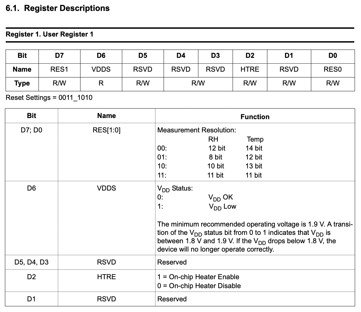
We’re going slightly beyond the scope of I2C, but I’ll just point out that you need to look elsewhere in the data sheet to learn what each bit in each of these control and status registers actually means. For example, if we scroll down to page 26, we can see what each bit in the control registers mean.
In User Register 1, bits 0 and 7 set the measurement resolution. That’s weird, right? This can be set to various resolutions, so that the measurement you get back has more or less bits.
Bit 6 is a VDD status register, bits 3, 4, 5 are reserved, bit 2 turns on/off the heater, and bit 1 is reserved. You can see that you must read the data sheet to know this stuff.
Turns out there’s a heater control register that lets you control how much current is used in the heater.
Generalizing
If we looked at a different data sheet, we’d get a different set of rules. You should expect something like 1 person-week to get a new device fired up.
And by the way, how would you start? You might read some device ID registers to see if they are what you expect. And then do stuff to the sensor and see how it responds. For this particular sensor, I streamed measurements to a console and breathed on it. I wanted to make sure temperature/humidity climbed as expected and then recovered.