Video discussion of the content on this page
Hardware Hookup
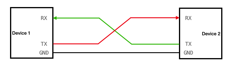
A UART channel has two data lines. On each device there is an RX pin and a TX pin (RX for receive and TX for transmit). The RX pin of each device is connected to the TX pin of the other. Note that there is no shared clock line! This is the "asynchronous" aspect of Universal Asynchronous Receiver Transmitter.
Timing Diagram
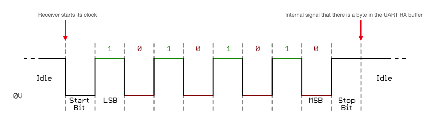
In an idle state, the Tx line from the sending device is held high. This is a legacy of old telegraph machines, for which the line is held high to make it obvious that it is not damaged. To send a packet, the transmitter first sends a start bit, which pulls the line low.
“UART” stands for Universal Asynchronous Receiver-Transmitter. The word “Asynchronous” in the name means that there is no shared clock between the transmitter and receiver. Instead, this start bit acts like a synchronization pulse between the transmitter and receiver. Each has their own clock, and they synchronize those clocks using the falling edge of this start bit.
That suggests that those two clocks need to running at the same speed. And indeed they do. These need to by synchronized to within ~2 percent or communication won’t work.
After this start bit 8 (or 9, depending on the configuration) bits are sent in least significant bit first format. At the end of the packet, there is a stop bit. The stop bit is one more down time followed by a rising edge. When the receiver sees the rising edge of that stop bit, it knows that there is now a valid character in its receive buffer and it will send some sort of internal signal to indicate as such. It may throw an interrupt, for example. It needs some sort of signal because this is asynchronous - a valid character could arrive at any time.
The number of clock pulses per bit can be configured to be 4 or 16. With only 4 pulses per bit, you can transmit faster, but you also only use a single sample per bit to determine whether a high or low level is present. With 16x the baud rate, majority detect circuitry is implemented to determine the value on the RX pin. The fastest that you can transmit is 1/4 the clock rate. So, at 40 MHz, you can in principle send data at up to 10Mbps, but don’t expect to be able to do that over very far distances.
Some things to notice about this protocol:
- It takes 10 bit-times to transmit 8-bits.
- It takes 1/(baud rate) seconds to transmit each bit
- The number of clock pulses per bit is configurable (4 or 16)
- You could transmit at up to 1/4 the clock rate, but not for very far distances
- Clock synchronization to within about 2 percent is required for successful communication
Error states
Framing errors
The UART status and control registers will indicate various status conditions, including error states associated with a transmission. Understanding this protocol makes understanding the error states a bit easier. They include framing errors, which occur when the receiver does not see a stop bit at the expected bit time. If the data line is not in the expected high state when the stop bit is expected (according to the number of data and parity bits for which the UART is set), the UART will signal a framing error.
Parity error
A parity error only gets thrown if the UART is in parity mode. In parity mode, an extra bit is sent which holds the parity (even or odd) of all of the transmitted data bits. If there is an error in a data bit (1 for 0 or 0 for 1), this parity bit will be wrong and an error will be thrown specifying an error.
Overrun error
An overrun error occurs when the receiver has not processed (removed characters from the input buffer) before the next character arrives.
Break condition
A break condition is not an error, necessarily. It occurs when the receiver input is at a logic level low state for longer than some duration of time, typically for more than a character time. It looks to the receiver like a character of all zero bits with a framing error. This is hacked for the software reset circuitry. In the python code, you can see that a reset is triggered by sending a break. This pulls the data line low for long enough that MCLR is pulled low and the board resets.
9-bit networking
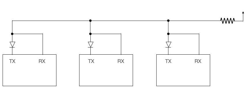
There is a configuration that allows you to setup a network that uses UART as the communication protocol. Doing so requires that all the lines of all the devices are wired together. There’s a diode going into each Tx line, and the whole thing is gently pulled up by a pull-up resistor.
This configuration means that a transmit pin can pull down the line, and the resistor will pull it back up. You then need a scheme for addressing a particular device from a particular device. A way to do this is to configure the UART to 9-bit mode (which means, as the name suggests, that 9 data bits are transmitted instead of 8). That 9th bit is then used to indicate whether the information that was just sent was an address or data.
If it was an address, then all secondary devices look for a match of their own hardcoded addresses. If they receive a match, they can be configured to automatically setup their receive/transmit functions. This address stays the bus address until a new address is sent. In other words, it’s persistent.