Digital lowpass filter implementation
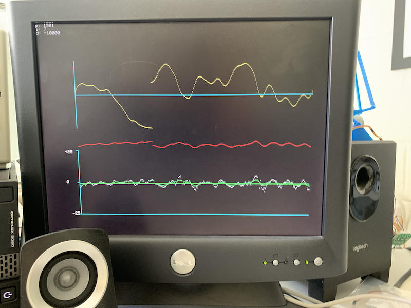
In the Reaction wheel inverted pendulum laboratory assignment, you are asked to display the accelerometer angle, gyro angle, complementary angle, and PID-computed control input on the VGA display. In the image below, the bottom plot shows angles (accelerometer in white, gyro in red, complementary in green), and the top plot shows the control input. Please note that the motor was off when I took this image (I simply moved the arm back and forth by hand), which is why there is so little noise on the accelerometer angles.
If you use a very large derivitive term in the PID controller to stabilize the oscillations, you may need to lowpass filter the motor signal to display on the scope. Consider using a first order IIR, digital lowpass, with a time constant of about 64 PWM samples, given by:
motor_disp = motor_disp + ((pwm_on_time - motor_disp)>>6) ;
(where pwm_on_time is the output of the PID controller, and motor_disp is the low-passed version that gets displayed). If you find that the signal still looks too noisy, increase the amount by which you shift the second term.
Why is does the above code work as a low-pass filter?
Why is this a low pass filter? We can arrive at the answer by considering a classic RC lowpass filter, as shown below:
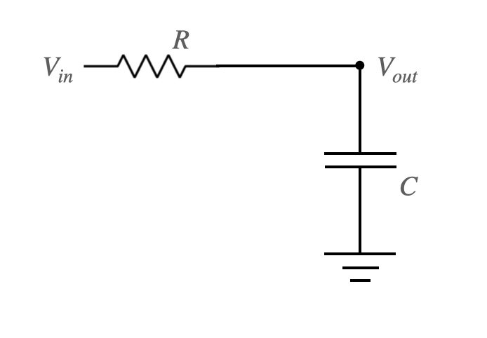
Because the resistor and capacitor are in series, we know that the current through each is the same:
\begin{align} i_r = \frac{V_{in} - V_{out}}{R} = i_c = C \frac{dV_{out}}{dt} \end{align}Rearrange to solve for $\frac{dV_{out}}{dt}$:
\begin{align} \frac{dV_{out}}{dt} &= \frac{1}{RC}\left(V_{in} - V_{out}\right) \end{align}Let us now discretize this equation. To do so, we'll use the following notation:
\begin{align} V_{out}(t) &= V^N\\ V_{out}(t+\Delta t) &= V^{N+1} \end{align}Taylor expand the second expression above:
\begin{align} V(t + \Delta t) &\approx V(t) + \left[\frac{dV_{out}}{dt}\right]_t\Delta t\\ \end{align}Using our notation, this becomes:
\begin{align} V^{N+1} &\approx V^N + \left[\frac{dV_{out}}{dt}\right]_t\Delta t\\ \end{align}Substitute the previous expression for $\frac{dV_{out}}{dt}$:
\begin{align} V^{N+1} &\approx V^N + \frac{\Delta t}{RC}\left(V_{in} - V^N\right) \end{align}The above expression maps directly to motor_disp = motor_disp + ((pwm_on_time - motor_disp)>>4) ;.
The time constant for the above lowpass filter is $RC$ seconds. However, if we change units from seconds to PWM units, the time constant is $\frac{RC}{\Delta t}$. So, if we shift-right by 4, then the above filter has a cutoff frequency at 16 PWM units. If we shift by 5, it has a cutoff frequency at 32 PWM units. And so on.