Introduction
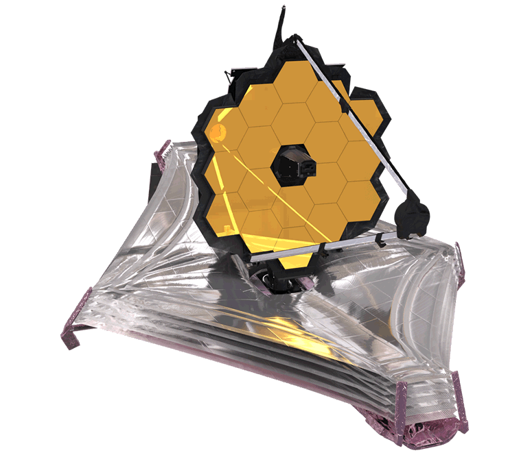
When the James Webb Space Telescope (or nearly any other modern spacecraft, for that matter) wants to change its orientation, how does it do so? It's not obvious how to turn something around in space where there's nothing (not even air) to push against. You might consider using thrusters, but those come at a cost! They require propellant. Propellant weighs a lot, and you can run out of it! A thruster shoots material into space when it fires, which can interfere with sensitive instrumentation. Furthermore, thruster fires tend to be impulsive in nature, which can excite vibrational modes in the spacecraft and don't allow for the ultra-precise control required to point at a distant star. Fortunately, thrusters aren't the only option for changing a spacecraft's orientation!
For changing the orbit of a spacecraft, you must have an external force (like a thruster) acting on the spacecraft. But to change the orientation of a spacecraft, we just need a torque! That torque might come from a thruster exerting a force, since $\bf{\tau} = \bf{F} \times \bf{r}$, but it can also come from a change in angular momentum, since $\tau = \frac{d \bf{L}}{dt}$. A spacecraft can change its orientation by storing angular momentum in an internal device, and then exchanging angular momentum between that device and the spacecraft body. Often, that device is a reaction wheel.
A reaction wheel is a heavy, spinning disc rigidly mounted inside the spacecraft. The reaction wheel + spacecraft is a closed system which must conserve angular momentum. So, if we make the reaction wheel spin slightly faster in the clockwise direction, the spacecraft body will compensate by spinning in the counterclockwise direction. Point a reaction wheel in each direction, and you've got 3-axis control! If you care to dive into the physics, please see here.
In this lab, we will use a PID controller to modulate the speed of a reaction wheel at the end of an inverted pendulum. The torque that the reaction wheel exerts on the pendulum will balance it. In order for this to work, we must close the loop around a measurement of the pendulum angle. This angle will be estimated using a complementary filter of accelerometer and gyroscope measurements from an IMU.
Key concepts: PID control, PWM, electrical isolation, complementary filters and sensor fusion, I2C, timers, timer interrupts, digital low-pass filtering, gyroscopes, accelerometers, UART, threading, VGA, fixed-point arithmetic
Demonstration
Please see demo video below.
Reading
Experience shows that students prefer these webpages short. For that reason, please find the reading and background materials on the webpages linked below. Please note that the information in these readings will be critical for completing the lab.
Engineering background
- Mechanical construction of the inverted pendulum: Procedure for building the inverted pendulum.
- Data display: Describes the data that you must visualize in realtime, and some strategies for visualizing that data (digital lowpass filters).
- Motor circuit and PWM: This webpage describes the circuit that you will construct to safely drive the DC motor, and how to generate PWM.
- Tuning the reaction wheel PID controller: This webpage describes a strategy for tuning your PID controller.
- VGA driver: You will not be asked to implement a VGA driver, you will use the one described on this webpage.
- MPU-6050 datasheet: The datasheet for the accelerometer/gyro that we'll be using.
- RP2040 datasheet: See sections on PWM and I2C.
- RP2040 C SDK: See sections on PWM and I2C.
Mathematical background
- Complementary filters: A method for estimating angle from gyroscope and accelerometer measurements. This is a great algorithm for your toolbox. Quick, easy, and effective.
- Phenomenological introduction to PID controllers: This webpage provides a phenomenological introduction to PID controllers, using a system that is different from this one.
- Analytical introduction to PID controllers: This webpage provides an analytical introduction to PID controllers, using a system that is different from this one.
- Reaction wheel attitude dynamics: The physics of spacecraft attitude dynamics and determination. Not required reading, but of potential interest.
Program organization
You may organize your program however you like. Here is a suggestion:
- Protothreads maintains the ISR-driven, millisecond-scale timing as part of the supplied system. Use this for all low-precision timing (can have several milliseconds jitter).
- PID ISR uses a timer or PWM interrupt to ensure an exact 1kHz control rate.
- Clears the interrupt flag
- Reads the MPU-6050 for accelerometer and gyro measurements
- Uses these measurements in a complementary filter to compute arm angle.
- Runs the PID control loop at 1000/sec using the angle measurements from the complementary filter and the desired angle
- Sets a hardware PWM signals using output-compare units to control the motor using the command:
pwm_set_chan_level(slice_num, PWM_CHAN_X[A or B], pwm_on_time);.
- Main sets up peripherals and protothreads then just schedules tasks, round-robin
- Thread 1
- Takes user input from the serial interface to setup PID parameters and the desired angle.
- Thread 2
- Diplays accelerometer angle, gyro angle, complementary angle, and low-passed control input on VGA display
Weekly checkpoints
Note that these checkpoints are cumulative. In week 2, for example, you must have also completed all of the requirements from week 1.
Week one checkpoint
By the end of the lab section in week one of the lab you must have:
- The mechanical assembly finished.
- The H-bridge motor circuit built.
- You must be able to control the motor speed open-loop through a command line interface. Start from this demo code.
- Display of the actual tilt angle (as calculated by a complementary filter of the accelerometer and gyro measurements) and the low-passed motor command signal on the VGA display. This is critical for debugging.
Week two checkpoint
By the end of the lab secton in week two of the lab you must have:
- Full closed-loop control of the motor (just proportional control is fine).
- A serial command line interface to set PID parameters.
Week three assignment
- Estimate the tilt angle of the inverted pendulum using a complementary filter, display the angle on the VGA screen..
- Format the set angle and PID parameters to display appropriate messages on the VGA display or the serial console.
- At any time, take commands from the serial interface to:
- Set the desired tilt angle
- Set the PID proportional gain
- Set the PID differential gain
- Set the PID integral gain
- The new values should take effect immediately
- One set of coefficients should produce balancing and minor disturbance rejection.
- Use a PID control algorithm to control the speed of the motor by producing a PWM drive to the optoisolators in the H-bridge motor circuit. PWM demo code here.
- Tune the PID algorithm so that the arm balances.
- Display the motor control value (not the raw PWM signal) on the VGA. Noise control on this signal is essential. If you cannot see the shape of the control signal, you will not get credit for this feature! You may need to combine DSP and analog filtering, depending on exactly how you build the circuit. See here.
- Display the actual tilt angle, from the complementary filter, on the VGA. If this signal is noisy, you need to find out why! A noisy input makes the control PID algorithm very hard to tune.
You will demo all of the features above to a course staff member. You program should not need to be reset during the demo.
Lab report
Your written lab report should include all the sections mentioned on the policy page, and:
- A schematic of the circuit you built
- How you selected the PID gains
- An image of your VGA display (showing control input and estimated angle) during balancing
- An image of your VGA display (showing control input and estimated angle) after an impulse (i.e. after smacking it with a pencil).
- A heavily commented listing of your code.