Overview of circuit
The motor circuit must protect the microcontroller from the large $L \frac{dI}{dt}$ voltage spikes that come off of a PWM-driven DC motor. The 4N35 optoisolator completely isolates the MCU from the motor. The capacitor in parallel with the motor provides a path to ground for high frequency noise, and the L9110 contains internal snubber diodes that provide a path to ground for reverse-polarity spikes coming off the motor.
Some of the components in this circuit may require some experimentation/trial and error. The resistor attached to the base of the 4N35 should be set for best falltime, probably ~1MOhm. The capacitor in parallel with the motor should by ceramic (electrolytics are too slow) and should start with a value ~0.1uF. If there is too much spike noise, this value can be increased.
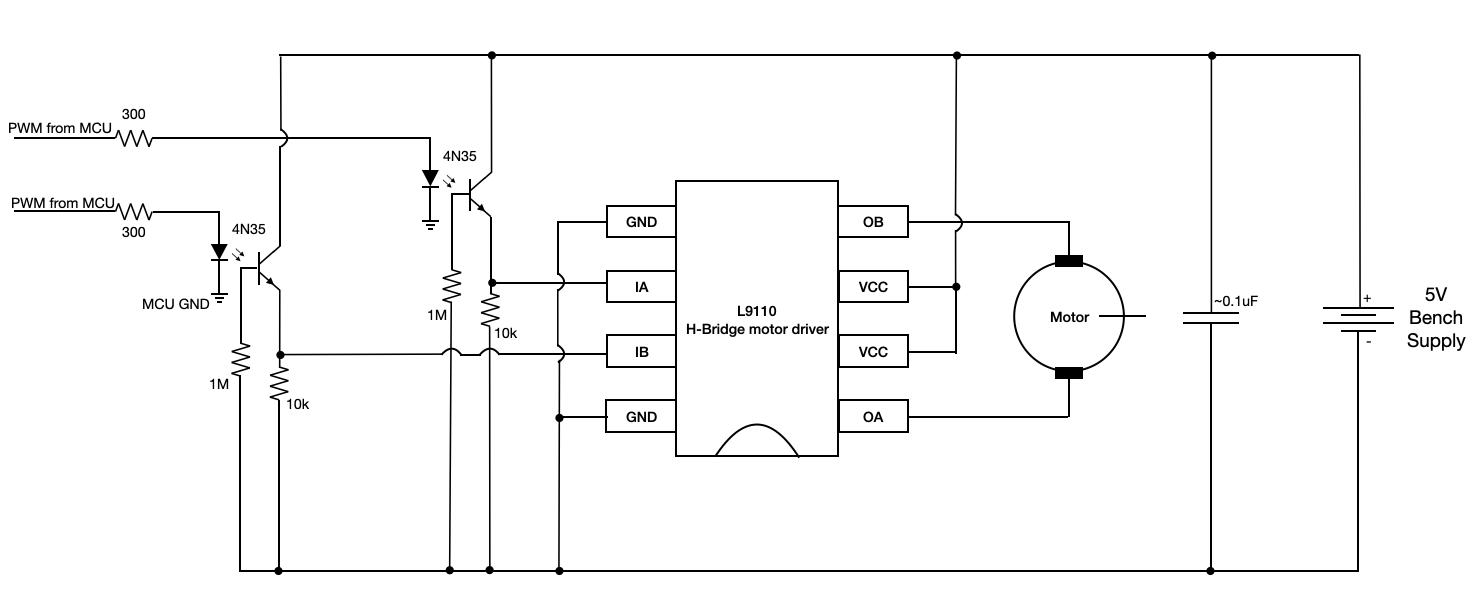
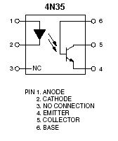
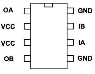
The pinouts for the 4N35 optoisolator and L9110 h-bridge motor driver are shown below. Note that it is the bandwidth of the 4N35 that constrains the PWM frequency. The bandwidth for this device is low, so we'll use a PWM frequency of about 1kHz.
 |
 |
Building and debugging the circuit
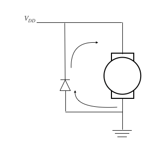
Do not build this whole circuit without testing as you go. Start by building the piece of the circuit indicated in the diagram below. Use the function generator to generate a PWM input, and use the oscilloscope to confirm that you're seeing a PWM output at the junction indicated.
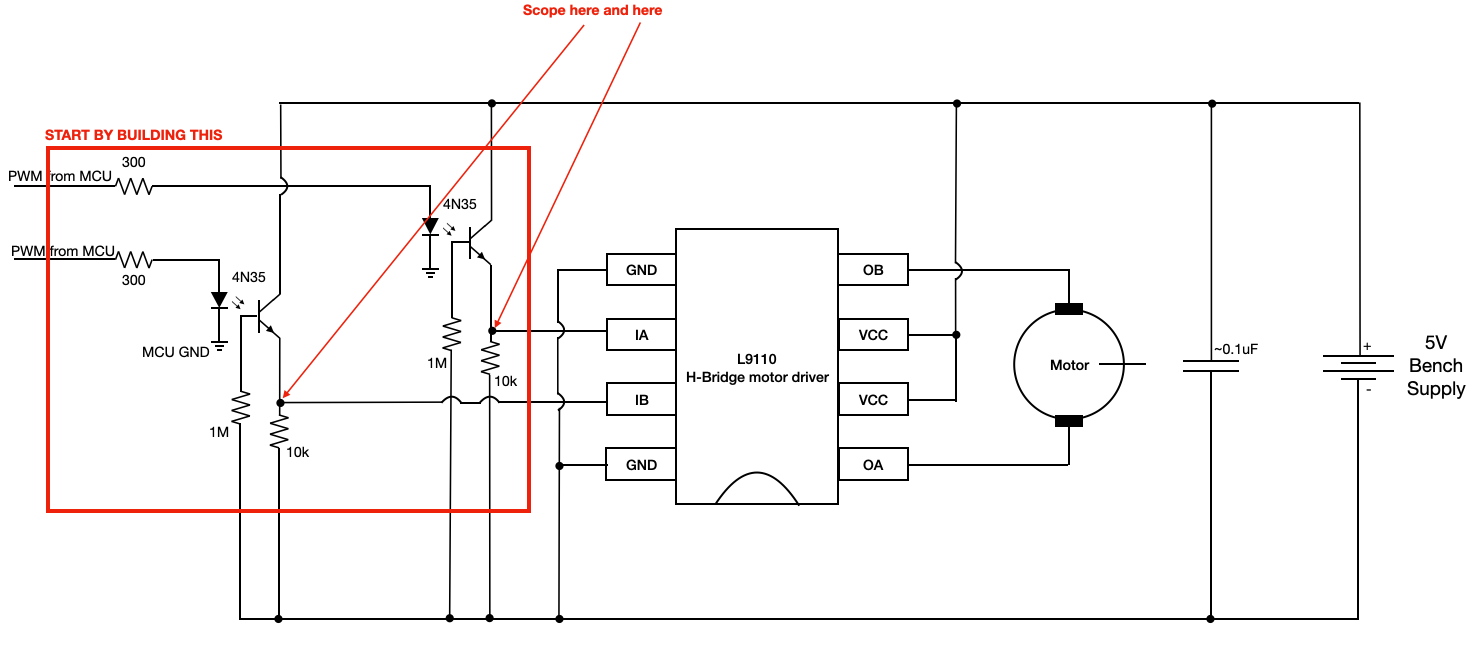
Only once you've confirmed that this part of the circuit works, add the rest.
Generating PWM
The PWM chapter in the RP2040 datasheet is short, read it!! The RP2040's PWM block is organized into "slices", each of which is connected to two GPIO ports. All 30 GPIO ports can be driven by the PWM block, but only 16 can be driven independently. Each PWM slice is equipped with a 16-bit counter, 8.4 fractional clock divider, two independent output channels, dual slope and trailing edge modulation, interrupt request and DMA request on counter wrap, and advanceable/retardable phase. Furthermore, each can be used in input mode to measure the duty cycle and frequency of an input signal.
The following code shows how to configure a PWM channel to throw an interrupt each time it wraps. We first map a particular GPIO (in this case, GPIO 5) to the PWM block. We use an SDK function to obtain the PWM slice associated with that GPIO (we could alternatively have looked this up in the datasheet). Then, we clear the interrupt associated with that GPIO slice, enable it, configure it such that it enters the ISR called on_pwm_wrap() each time the PWM wraps, end then enable the interrupt with the PWM_IRQ_WRAP interrupt flag.
Finally, we configure the wrapvalue and clock divider for the PWM channel, set the level (i.e. duty cycle) and start the channel.
Depending what you're trying to do with the PWM channel, you might omit some of these configurations.
////////////////////////////////////////////////////////////////////////
///////////////////////// PWM CONFIGURATION ////////////////////////////
////////////////////////////////////////////////////////////////////////
// Tell GPIO 5 that it is allocated to the PWM
gpio_set_function(5, GPIO_FUNC_PWM);

// // Find out which PWM slice is connected to GPIO 5 (it's slice 2)
slice_num = pwm_gpio_to_slice_num(5);

// Mask our slice's IRQ output into the PWM block's single interrupt line,
// and register our interrupt handler
pwm_clear_irq(slice_num);
pwm_set_irq_enabled(slice_num, true);
irq_set_exclusive_handler(PWM_IRQ_WRAP, on_pwm_wrap);
irq_set_enabled(PWM_IRQ_WRAP, true);

// This section configures the period of the PWM signals
pwm_set_wrap(slice_num, WRAPVAL) ;
pwm_set_clkdiv(slice_num, CLKDIV) ;

// This sets duty cycle
pwm_set_chan_level(slice_num, PWM_CHAN_B, 3125);

// Start the channel
pwm_set_mask_enabled((1u << slice_num));
With the configurations shown above, we also need to define the interrupt service routine. At minimum, the ISR must clear the interrupt flag, as shown below.
void on_pwm_wrap() {
    // Clear the interrupt flag that brought us here
    pwm_clear_irq(pwm_gpio_to_slice_num(5));
}
Here is some demo code which asks the user to specify a duty cycle, and then sets a PWM output to that duty cycle.
Why are we using this circuit?
The circuit above protects the microcontroller from the noise that the DC motor generates. To understand this circuit, we must understand the nature of this noise. This requires a brief discussion of the internal mechanisms in the motor.
Internal mechanism
A DC motor works by setting up a magnetic field, using either permanent magnets or electromagnets. Inside of this magnetic field is a coil of wire called an armature. The motor drives current in a particular direction through this coil of wire. Any current-carrying conductor placed within a magnetic field experiences a force (Lorentz) and thus the armature begins to turn. Halfway through its turn, the commutator switches the direction of current through the armature so that the torque remains in the same direction.

Because the armature is a conductor moving through a magnetic field, an emf is induced on the armature as in a generator. The faster that the armature is rotating, the greater the back-emf. This back-emf regulates the current through the armature. When the motor is spinning at a constant rate and the load isn't changing, the back emf is approximately equal to the supply voltage. If a load is added to the motor, then the speed of the motor drops. This leads to a corresponding drop in the back emf, which leads to greater current through the armature and higher torque from the motor. If the load is reduced, the motor speeds up. This increases the back emf and decreases the torque from the motor in favor of speed.
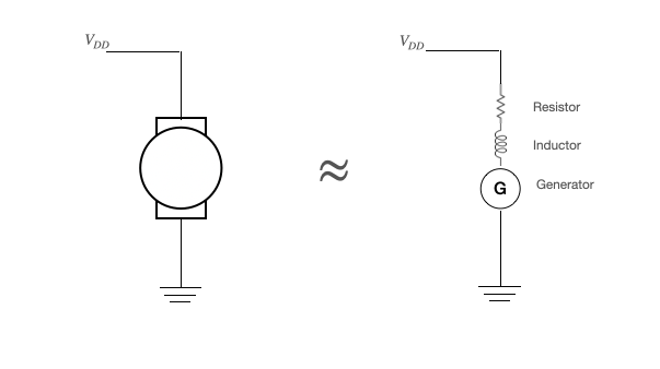
Motor model
We can therefore approximate the motor as a resistor in series with an inductor (the armature) in series with a generator. More detail available here.
Motor noise
Suppose that we drive this motor using a PWM signal. We are therefore rapidly changing the current through an inductor. Recall that the voltage across an inductor is given by:
\begin{align} V &= L\cdot \frac{dI}{dt} \end{align}Suppose a modest DC motor with an inductance of 1mH that pulls ~1A, and suppose that we drive this motor with a PWM signal that opens a switch to the motor in ~10ns. What voltage should we expect across the inductor?
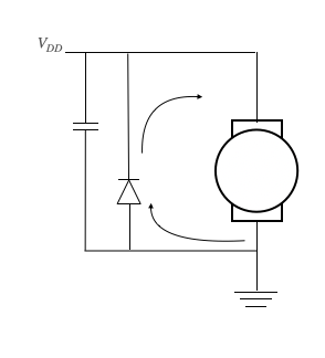
\begin{align} V &= L \cdot \frac{dI}{dt}\\ &= 10^{-3} \cdot \frac{1}{10^{-8}}\\ &= 10^5V \end{align}The voltage across the motor changes polarity and becomes huge. This can destroy other devices that are a part of the circuit. For this reason, we include a snubber diode in parallel with the motor, which provides a safe path to ground for this reversed-polarity current. This snubber must be physically large enough to absorb the energy from the motor.
In addition to this large voltage spikes, the brushes in DC motors kick off a huge amount of high frequency (>100kHz) noise on Vdd. We attenuate this noise with a bypass capacitor. The video below shows a demonstration of this noise, and of the noise being attenuated with a cap.
Even with these protective components in place, it is a good idea to completely electrically isolate the motor from the CPU (different Vdd, different ground). This can be achieved with an optical isolator like the 4N35 in the circuit diagram at the top of this page.