Mechanical construction of inverted pendulum
V. Hunter Adams
This webpage describes the mechanical construction of the inverted pendulum for the reaction wheel lab. The necessary materials include:
- Lasercut acrylic arm (x1) (x1)
- 3D printed reaction wheel - designed by Smith Charles
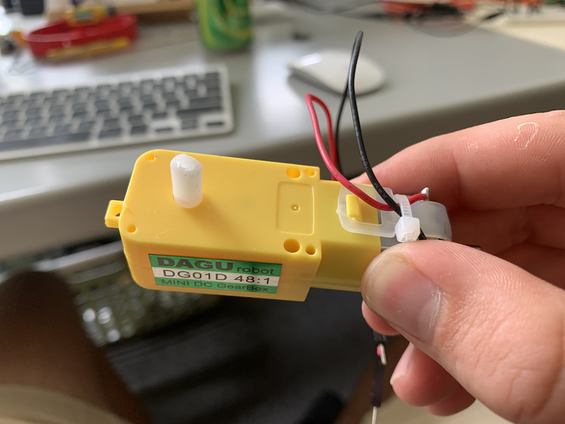
- Hobby gearmotor (x1)
- MPU-6050 IMU breakout board (x1)
- Clamps (x2)
- Lego bricks
- 10-32 screw (x1)
- 10-32 nut or wingnut (x1)
- M2.5 screw (x4)
- M3 nuts (x4)
- M2.5 screw (x2)
- M3 nut or wingnut (x2)
Procedure
The pendulum construction is straightforward, but going in order is helpful for making deconstruction as easy as possible. If you're not careful, you can end up making the device difficult to take apart.
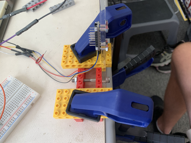
1. Attach the motor to the arm
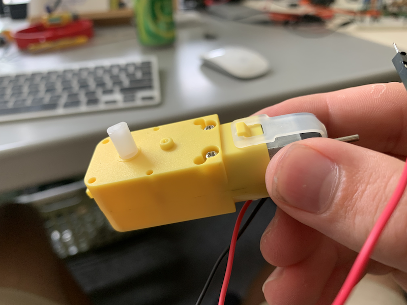
On the gearmotors, there is a flat side and a side with a bump (see pictures below).
 |
 |
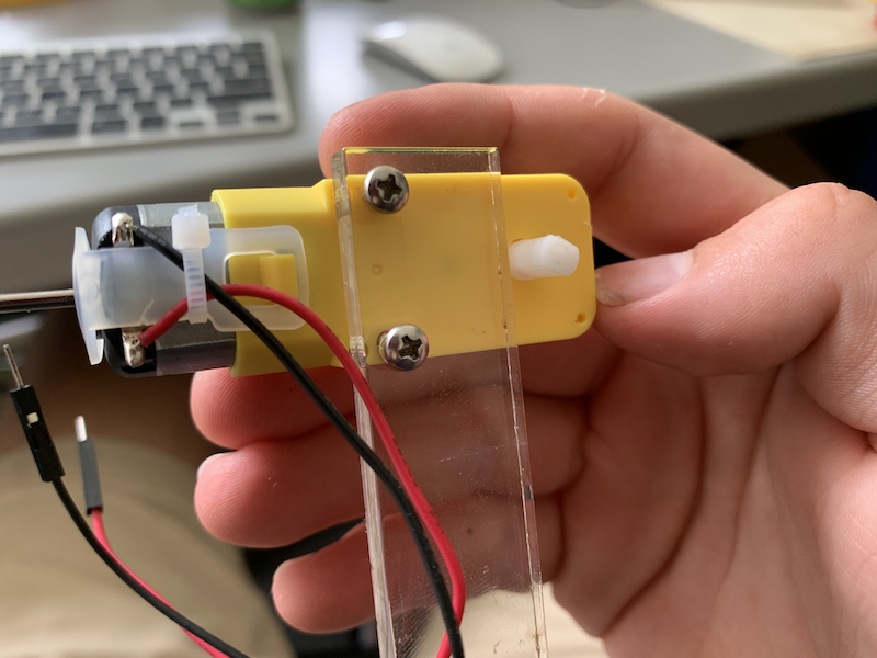
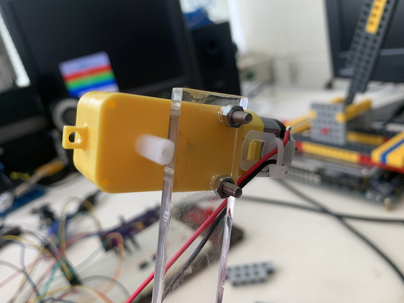
Align the holes at the top of the acrylic arm with the holes on the flat side of the gearmotor, and thread two M3 screws through the acrylic and gearmotor. Secure them with nuts or wingnuts. See pictures below.
 |
 |
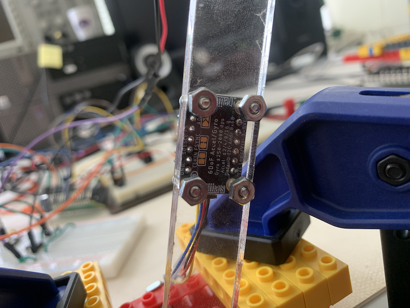
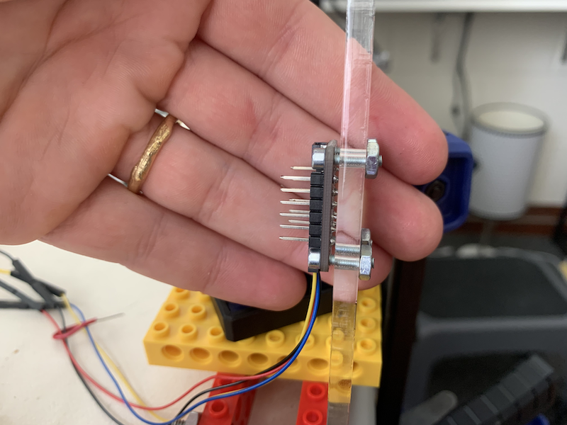
2. Attach the IMU to the arm
Align the MPU-6050 breakout board with the four holes farther down the acrylic arm. Place the IMU on the same side of the arm as the gearmotor. Thread four M2.5 screws through the breakout board and acrylic arm, then secure with nuts or wingnuts. Ask for a Qwic connector for easier wiring.
 |
 |
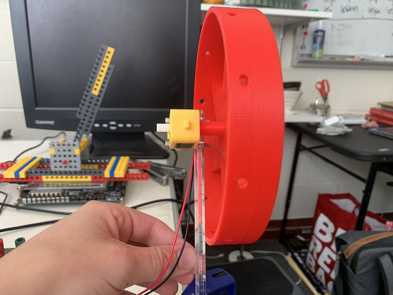
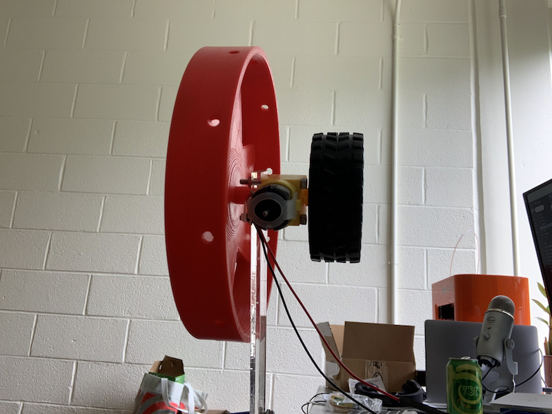
3. Attach reaction wheel to gearmotor
Press the reaction wheel onto the gearmotor on the opposite side of the acrylic arm as the gearmotor body. This is a very snug fit. Please don't remove the reaction wheel once it's attached. If the wheel is rubbing against the acrylic arm, put a piece of electrical tape on the arm against which the wheel can slide. Otherwise it's very loud and annoying.
 |
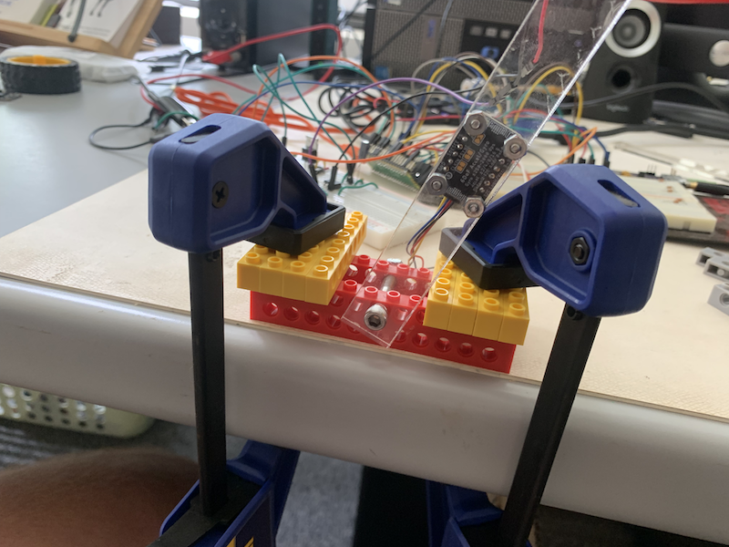
4. Attach arm to Lego base
Build the simple Lego base shown below (two parallel bricks of height two, with platforms on each side. Use the clamps to hold the base to the edge of the table. Thread a 10-32 screw through the acrylic arm, through the first row of bricks, and through the second row of bricks. Secure in place with a nut (but don't tighten too much! We want the arm to rotate freely. Make sure your Lego base has rotation stops.
 |
 |
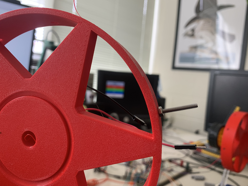
5. (Possibly) tune for balance
You can add a wheel to the reverse side of the arm, and/or screws around the exterior of the reaction wheel to improve its balance.
 |
 |
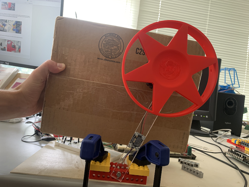
6. Finished system
Pictured below. Cardboard box just to make the system more visible.
 |