Direct Digital Synthesis (DDS) in a Timer Interrupt on the RP2040
V. Hunter Adams (vha3@cornell.edu)
Objective and page organization
This project contains a simple example of setting up a timer interrupt and an SPI channel on the RP2040. In particular, the RP2040 communicates with an SPI DAC, and uses Direct Digital Synthesis to generate an 800Hz sine thru the DAC.
All of the code is provided in a listing in the first section of this page. The rest of the page walks through the C source file from top to bottom, explaining each line of code.
Please see the C SDK guide and the RP2040 datasheet.
All the code
/**
 * V. Hunter Adams
 * DDS of sine wave on MCP4822 DAC w/ ISR
 *
 * Modified example code from Raspberry Pi
 * Copyright (c) 2020 Raspberry Pi (Trading) Ltd.
 *
 * SPDX-License-Identifier: BSD-3-Clause
 *
   GPIO 5 (pin 7) Chip select
   GPIO 6 (pin 9) SCK/spi0_sclk
   GPIO 7 (pin 10) MOSI/spi0_tx
   GPIO 2 (pin 4) GPIO output for timing ISR
   3.3v (pin 36) -> VCC on DAC
   GND (pin 3)  -> GND on DAC
 */

#include <stdio.h>
#include <math.h>
#include "pico/stdlib.h"
#include "hardware/timer.h"
#include "hardware/irq.h"
#include "hardware/spi.h"

// Low-level alarm infrastructure we'll be using
#define ALARM_NUM 0
#define ALARM_IRQ TIMER_IRQ_0

//DDS parameters
#define two32 4294967296.0 // 2^32
#define Fs 50000
#define DELAY 20 // 1/Fs (in microseconds)
// the DDS units:
volatile unsigned int phase_accum_main;
volatile unsigned int phase_incr_main = (800.0*two32)/Fs ;//
// DDS sine table
#define sine_table_size 256
volatile int sin_table[sine_table_size] ;

// SPI data
uint16_t DAC_data ; // output value

//DAC parameters
// A-channel, 1x, active
#define DAC_config_chan_A 0b0011000000000000
// B-channel, 1x, active
#define DAC_config_chan_B 0b1011000000000000

//SPI configurations
#define PIN_MISO 4
#define PIN_CS   5
#define PIN_SCK  6
#define PIN_MOSI 7
#define SPI_PORT spi0

//GPIO for timing the ISR
#define ISR_GPIO 2

// Alarm ISR
static void alarm_irq(void) {

    // Assert a GPIO when we enter the interrupt
    gpio_put(ISR_GPIO, 1) ;

    // Clear the alarm irq
    hw_clear_bits(&timer_hw->intr, 1u << ALARM_NUM);

    // Reset the alarm register
    timer_hw->alarm[ALARM_NUM] = timer_hw->timerawl + DELAY ;

    // DDS phase and sine table lookup
    phase_accum_main += phase_incr_main  ;
    DAC_data = (DAC_config_chan_A | ((sin_table[phase_accum_main>>24] + 2048) & 0xffff))  ;

    // Perform an SPI transaction
    spi_write16_blocking(SPI_PORT, &DAC_data, 1) ;

    // De-assert the GPIO when we leave the interrupt
    gpio_put(ISR_GPIO, 0) ;

}

int main() {
    // Initialize stdio
    stdio_init_all();
    printf("Hello, DAC!\n");

    // Initialize SPI channel (channel, baud rate set to 20MHz)
    spi_init(SPI_PORT, 20000000) ;
    // Format (channel, data bits per transfer, polarity, phase, order)
    spi_set_format(SPI_PORT, 16, 0, 0, 0);

    // Setup the ISR-timing GPIO
    gpio_init(ISR_GPIO) ;
    gpio_set_dir(ISR_GPIO, GPIO_OUT);
    gpio_put(ISR_GPIO, 0) ;

    // Map SPI signals to GPIO ports
    gpio_set_function(PIN_MISO, GPIO_FUNC_SPI);
    gpio_set_function(PIN_SCK, GPIO_FUNC_SPI);
    gpio_set_function(PIN_MOSI, GPIO_FUNC_SPI);
    gpio_set_function(PIN_CS, GPIO_FUNC_SPI) ;

    // === build the sine lookup table =======
    // scaled to produce values between 0 and 4096
    int ii;
    for (ii = 0; ii < sine_table_size; ii++){
         sin_table[ii] = (int)(2047*sin((float)ii*6.283/(float)sine_table_size));
    }

    // Enable the interrupt for the alarm (we're using Alarm 0)
    hw_set_bits(&timer_hw->inte, 1u << ALARM_NUM) ;
    // Associate an interrupt handler with the ALARM_IRQ
    irq_set_exclusive_handler(ALARM_IRQ, alarm_irq) ;
    // Enable the alarm interrupt
    irq_set_enabled(ALARM_IRQ, true) ;
    // Write the lower 32 bits of the target time to the alarm register, arming it.
    timer_hw->alarm[ALARM_NUM] = timer_hw->timerawl + DELAY ;

    // Nothing happening here
    while(1){
    }
    return 0;
}
Stepping thru the code
Let us step through each section of code, explaining and justifying each line.
Includes
#include <stdio.h>
#include <math.h>
#include "pico/stdlib.h"
#include "hardware/timer.h"
#include "hardware/irq.h"
#include "hardware/spi.h"
The first lines of code in the C source file include some header files. Two of these are standard C headers (stdio.h and math.h) and the others are headers which come from the C SDK for the Raspberry Pi Pico. The first of these, pico/stdlib.h is what the SDK calls a "High-Level API." These high-level API's "provide higher level functionality that isn’t hardware related or provides a richer set of functionality above the basic hardware interfaces." The architecture of this SDK is described at length in the SDK manual. All libraries within the SDK are INTERFACE libraries. pico/stdlib.h in particular pulls in a number of lower-level hardware libraries, listed on page 196 of the C SDK guide.
The next includes pull in the hardware interface library for the SPI hardware peripheral, the low-level timer interface, and the low-level interrupt interface. Don't forget to link these in the CMakeLists.txt file!
Alarms
// Low-level alarm infrastructure we'll be using
#define ALARM_NUM 0
#define ALARM_IRQ TIMER_IRQ_0
There are actually a few different timers in the RP2040. There is a single 64-bit counter, which increments once per microsecond. The PWM also has 8x16-bit programmable counters, the PIO state machines can be setup as timers, and the DMA has four internal pacing timers. The Alarm infrastructure uses that incrementing 64-bit counter.
The least significant 32 of these 64 bits lives in one register, and the most significant 32 bits lives in another. There are four timer interrupts (TIMER_IRQ_0, TIMER_IRQ_1, TIMER_IRQ_2, TIMER_IRQ_3). Each of these interrupts fires when there is a match between the associated ALARM register and the lower 32 bits of the microsecond timer. See page 537 of the datasheet.
We are going to use Alarm register 0, which maps to TIMER_IRQ_0. In the associated timer interrupt, we'll re-write the alarm register so that the interrupt fires again at the specified amount of time in the future. We'll have the interrupt fire every 20us, for a 50kHz synthesis rate.
DDS globals
//DDS parameters
#define two32 4294967296.0 // 2^32
#define Fs 50000
#define DELAY 20 // 1/Fs (in microseconds)

// the DDS units:
volatile unsigned int phase_accum_main;
volatile unsigned int phase_incr_main = (800.0*two32)/Fs ;//
// DDS sine table

#define sine_table_size 256
volatile int sin_table[sine_table_size] ;
The next chunk of code defines and declares a series of variables which will be used for Direct Digital Synthesis. For an extended explanation of the DDS algorithm, please see this webpage. The sine table is populated in main().
SPI globals
// SPI data
uint16_t DAC_data ; // output value

//DAC parameters
// A-channel, 1x, active
#define DAC_config_chan_A 0b0011000000000000
// B-channel, 1x, active
#define DAC_config_chan_B 0b1011000000000000

//SPI configurations
#define PIN_MISO 4
#define PIN_CS   5
#define PIN_SCK  6
#define PIN_MOSI 7
#define SPI_PORT spi0
We declare a uint16_t variable which will be used to communicate over the SPI channel to the DAC (the DAC expects 16-bit transfers, hence the type uint16_t). The next lines of code sets the top 4 DAC configuration bits for both channels A and B. You can read about these configuration bits in the DAC datasheet, but note that the bottom 12 bits of DAC_config_chan_A and DAC_config_chan_B are all 0's. In the Timer ISR, we will mask the DAC data into these bottom 12 bits, maintaining the top 4 control bits.
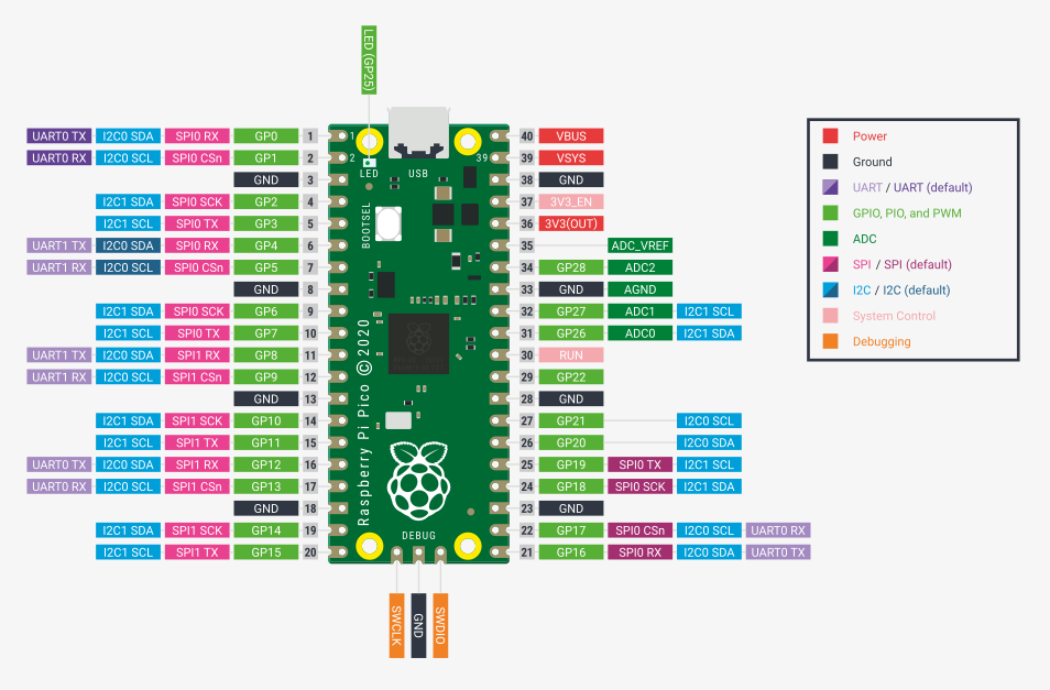
The next chunk of code gives some names to a handful of GPIO ports for later association with the SPI channel. Note that the numbers in these lines of code correspond to GPIO port number and not to pin numbers. Note also that these pins are not chosen arbitrarily. We've chosen a particular set of GPIO ports which are all associated with the same SPI channel (SPI0), and named each according to its available function on that SPI channel (MISO/RX, MOSI/TX, CS, SCK). We could have chosen different GPIO ports for each of these functions, but not arbitrary ports, only those with the same signals mapped to them. We can determine which GPIO's are available for mapping to which hardware peripherals by looking at Fig. 2 of the Raspberry Pi Pico datasheet (also included below) or at the Function Select Table on page 111 of the C SDK manual.
The final line in this chunk specifies the SPI channel which we are using, which is spi0. spi0 is declared in the spi.h header file (pico-sdk\src\rp2_common\hardware_spi\include\hardware\spi.h).
GPIO for ISR timing
#define ISR_GPIO 2
We'll use GPIO 2 to time our ISR entries. We'll toggle it high at the start of the ISR, and low at the end. This way we can use the oscilloscope to measure how much time we're spending in the interrupt, and to confirm that we're re-entering the interrupt with the desired timing.
Timer callback function
// Alarm ISR
static void alarm_irq(void) {

    // Assert a GPIO when we enter the interrupt
    gpio_put(ISR_GPIO, 1) ;

    // Clear the alarm irq
    hw_clear_bits(&timer_hw->intr, 1u << ALARM_NUM);

    // Reset the alarm register
    timer_hw->alarm[ALARM_NUM] = timer_hw->timerawl + DELAY ;

    // DDS phase and sine table lookup
    phase_accum_main += phase_incr_main  ;
    DAC_data = (DAC_config_chan_A | ((sin_table[phase_accum_main>>24] + 2048) & 0xffff))  ;

    // Perform an SPI transaction
    spi_write16_blocking(SPI_PORT, &DAC_data, 1) ;

    // De-assert the GPIO when we leave the interrupt
    gpio_put(ISR_GPIO, 0) ;

}
Above is a callback function associated with the timer alarms on core 0. In this callback, we raise the GPIO we're using for ISR timing, clear the interrupt, reset the alarm register, the phase accumulator is incremented and used to index into the sine table, and a single SPI write is performed.
Main
int main() {
    // Initialize stdio
    stdio_init_all();
    printf("Hello, DAC!\n");

    // Initialize SPI channel (channel, baud rate set to 20MHz)
    spi_init(SPI_PORT, 20000000) ;
    // Format (channel, data bits per transfer, polarity, phase, order)
    spi_set_format(SPI_PORT, 16, 0, 0, 0);

    // Setup the ISR-timing GPIO
    gpio_init(ISR_GPIO) ;
    gpio_set_dir(ISR_GPIO, GPIO_OUT);
    gpio_put(ISR_GPIO, 0) ;

    // Map SPI signals to GPIO ports
    gpio_set_function(PIN_MISO, GPIO_FUNC_SPI);
    gpio_set_function(PIN_SCK, GPIO_FUNC_SPI);
    gpio_set_function(PIN_MOSI, GPIO_FUNC_SPI);
    gpio_set_function(PIN_CS, GPIO_FUNC_SPI) ;

    // === build the sine lookup table =======
    // scaled to produce values between 0 and 4096
    int ii;
    for (ii = 0; ii < sine_table_size; ii++){
         sin_table[ii] = (int)(2047*sin((float)ii*6.283/(float)sine_table_size));
    }

    // Enable the interrupt for the alarm (we're using Alarm 0)
    hw_set_bits(&timer_hw->inte, 1u << ALARM_NUM) ;
    // Associate an interrupt handler with the ALARM_IRQ
    irq_set_exclusive_handler(ALARM_IRQ, alarm_irq) ;
    // Enable the alarm interrupt
    irq_set_enabled(ALARM_IRQ, true) ;
    // Write the lower 32 bits of the target time to the alarm register, arming it.
    timer_hw->alarm[ALARM_NUM] = timer_hw->timerawl + DELAY ;

    // Nothing happening here
    while(1){
    }
    return 0;
}
Initialize UART
// Initialize stdio
stdio_init_all();
printf("Hello, DAC!\n");
The entry point for core 0 is main(). This function calls stdio_init_all() to setup stdio/uart on the RP2040 and prints a greeting.
SPI initialization and configuration
// Initialize SPI channel (channel, baud rate set to 20MHz)
spi_init(SPI_PORT, 20000000) ;
// Format (channel, data bits per transfer, polarity, phase, order)
spi_set_format(SPI_PORT, 16, 0, 0, 0);
To setup the SPI channel, we first call spi_init(), which takes two arguments. The first is the name of the spi channel (which we'd previously defined to spi0, and the second is the baud rate for the channel. Per the DAC datasheet, this is configured to 20MHz. Note that an SPI channel must be initialized before it is configured, which is what happens in the second line of code. For more information about SPI, please see here.
spi_set_format configures the SPI channel to whichever mode the device with which the RP2040 is communicating requires. static void spi_set_format (spi_inst_t \*spi, uint data_bits, spi_cpol_t cpol, spi_cpha_t cpha, __unused spi_order_t order) takes 4 arguments. The first is the SPI instance specifier. The second is the number of data bits per transfer. Since the DAC expects 16 bit transfers, this is configured to 16. CPOL and CPHA set the SPI clock polarity and phase (i.e. the "mode"). Finally order is not presently configurable, but sets the endianness of the transfer. Sends MSB first.
GPIO Mapping
// Setup the ISR-timing GPIO
gpio_init(ISR_GPIO) ;
gpio_set_dir(ISR_GPIO, GPIO_OUT);
gpio_put(ISR_GPIO, 0) ;

// Map SPI signals to GPIO ports
gpio_set_function(PIN_MISO, GPIO_FUNC_SPI);
gpio_set_function(PIN_SCK, GPIO_FUNC_SPI);
gpio_set_function(PIN_MOSI, GPIO_FUNC_SPI);
gpio_set_function(PIN_CS, GPIO_FUNC_SPI) ;
We next set up our GPIO's. We first initialize the ISR_GPIO (this maps it to the SIO) and set it as an output before setting its value to 0.
The next chunk of code is a series of calls to gpio_set_function(). Each of these calls maps a particular GPIO port (#define'd above) to a particular function. This takes two arguments. The first is the GPIO number, and the second specifies the function. The function specifier comes from the enum listed below:
enum gpio_function { GPIO_FUNC_XIP = 0, GPIO_FUNC_SPI = 1, GPIO_FUNC_UART = 2, GPIO_FUNC_I2C = 3, GPIO_FUNC_PWM = 4, GPIO_FUNC_SIO = 5, GPIO_FUNC_PIO0 = 6, GPIO_FUNC_PIO1 = 7, GPIO_FUNC_GPCK = 8, GPIO_FUNC_USB = 9, GPIO_FUNC_NULL = 0xf }
Something to note! We are mapping the chip select line here. If instead we made the chip select line a digital output pin, we would need to toggle it in software before and after each SPI transmission. Configured as shown here, the SPI channel is setup in a way that is very similar to "Framed SPI Mode" for the PIC32." That is, the RP2040 will automatically toggle the chip select line if it is mapped using gpio_set_function. Not every pin can be mapped to every function! Double check the datasheet and pinout!
Building the sine table
// === build the sine lookup table =======
// scaled to produce values between 0 and 4096
int ii;
for (ii = 0; ii < sine_table_size; ii++){
     sin_table[ii] = (int)(2047*sin((float)ii*6.283/(float)sine_table_size));
}
This chunk of code populates the sin_table array. For convenience, this sine table is scaled to [-2047, 2047]. In the Timer ISR, we add 2047 to this sine table to send a value to the DAC that is in the range [0, 4096].
Setup the alarm interrupt
// Enable the interrupt for the alarm (we're using Alarm 0)
hw_set_bits(&timer_hw->inte, 1u << ALARM_NUM) ;
// Associate an interrupt handler with the ALARM_IRQ
irq_set_exclusive_handler(ALARM_IRQ, alarm_irq) ;
// Enable the alarm interrupt
irq_set_enabled(ALARM_IRQ, true) ;
// Write the lower 32 bits of the target time to the alarm register, arming it.
timer_hw->alarm[ALARM_NUM] = timer_hw->timerawl + DELAY ;
The final chunk of setup code in main sets up the alarm interrupt. The first line masks a 1 into the INTE register bit associated with hardware alarm 0. See page 545 of the datasheet. This tells the alarm to enable this interrupt, we still need to enable the associated interrupt for the processor, and to associate that interrupt with an interrupt service routine.
The next line associated the function named alarm_irq (discussed earlier) with the ALARM_IRQ register. In the #define's at the top of the file, we associated this with TIMER_IRQ_0.
The next line turns on TIMER_IRQ_0 for the processor. Now the interrupt is enabled for both the peripheral and the processor.
The final line writes a value to the ALARM0 register, which arms it. When there is a match between the value written to this register and the lower 32 bits of the incrementing 64-bit microsecond timer, the interrupt service routine will fire. Note that we have set this value to the current value of the timer (contained in timer_hw->timerawl) plus our 20us DELAY.
Spin forever
Finally, we enter a while(1) loop from which we never exit.
while(1){
}
return 0;
It’s quite common for the main() function not to return. The return code of main() is ignored by the SDK runtime, and the default behavior is to hang the processor on exit.
CMakeLists.txt
Note that we have added hardware_spi to the linked libraries!
add_executable(dactest dactest.c)

pico_add_extra_outputs(dactest)

target_link_libraries(dactest pico_stdlib hardware_spi)
Documentation
- Please see the C SDK guide and the RP2040 datasheet.
- Please see the DDS webpage
- Please see the SPI webpage