Project Code and Demo
The resistive touchscreen
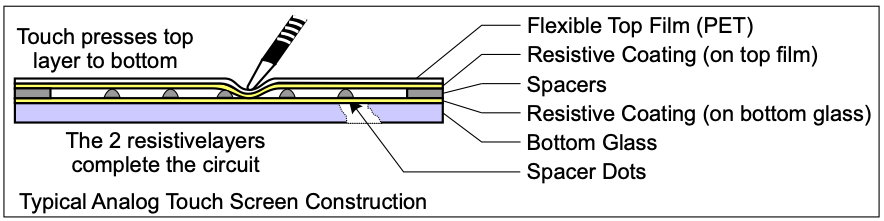
As described in this document, the resistive touchscreen is a layered 2D device. It is composed of a top PET layer with a resistive coating separated from a bottom resistive layer by spacers. When the user presses on the top of the screen, contact is made between the top and bottom resistive coatings, completing the circuit. The measured resistance through the completed circuit depends on the position of the press, enabling determination of the precise location of the press in both dimensions.
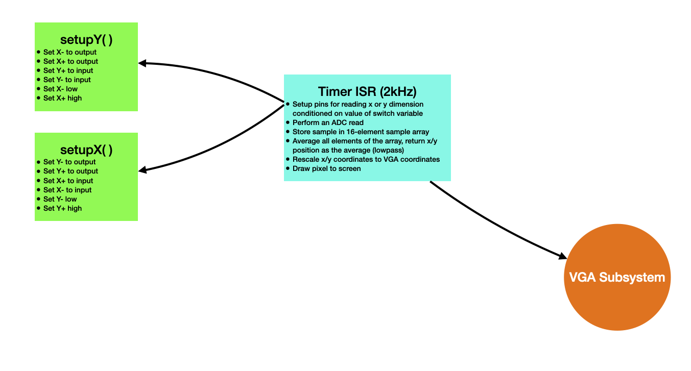
Four pins are required in order to drive this screen, and the functions of those pins must be switched dynamically. Each pin is connected to a conductive pad on one of the four sides of the screen (+x, -x, +y, -y). In order to read the x-position of a press, y+ is set high, y- is set to ground, x- is left floating (set to input), and the ADC is used to measure x+. In order to measure the y-position of the press, x+ is set high, x- is set to ground, y- is left floating (set to input), and the ADC is used to measure y+. So, all pins must be switched between output and input.
Code organization
There is a single timer interrupt running at 2kHz. Depending on the value of a switching variable, this ISR configures and reads the x or y coordinate of a touch event and draws a pixel to the VGA display at the appropriate location. For more information on the VGA system, see here.