Wireless worm-like bootloader for RP2040
V. Hunter Adams
Introduction
A computer worm is a program that replicates and propagates itself across a network. Typically associated with malware, this project deploys a worm for good! In applications that involve a large number of independent microcontroller-based devices (e.g. swarm robotics or virtual cattle fencing), the bottleneck in the research and development process can be the time that it takes to plug-in/reprogram each individual device.
One scalable approach to reprogramming a huge collection of devices is to reprogram a single device, and to have that program spread (like a virus or a computer worm) to other devices that it encounters. You then get an exponential spread of firmware updates across the swarm.
This webpage describes a custom bootloader that allows for firmware updates to propagate from device to device. The particular mechanism for wireless data transfer in this project is infrared, though the bootloader is written so that it could be modified for radio, BLE, LoRA, or something else.
This project is an augmentation of a previous project: a custom serial bootloader for the RP2040.
Preliminary reading
In order to avoid bloating this webpage too much, I've consolidated prerequisite reading onto a few other webpages. I strongly encourage folks to read these other webpages before returning to this one.
- RP2040 boot sequence: This project modifies the default boot sequence for the RP2040. I think it's best understood if the reader has a cursory understanding of the default boot sequence.
- Custom serial bootloader for the RP2040: The first step for generating a worm-like bootloader was to generate a custom serial bootloader. The worm is an augmentation of the custom serial bootloader described on this webpage.
- Wireless UART via infrared: This webpage describes the particular mechanism for wireless information transfer used in this demonstration.
Modifying the serial bootloader
This webpage describes a custom serial bootloader which we will modify so that it behaves like a worm. As described on that webpage, this serial bootloader lives directly above the stage 2 bootloader in RP2040 memory, and receives new executable programs via a wireless UART interface. This bootloader has the ability to replace existing user application code, and it has the ability to detect and branch to valid programs in flash memory. The user can force the device into bootloader mode via a GPIO port, or an application program can force the device into bootloader mode by writing to a watchdog scratch register and then executing a soft reset.
When the system comes out of reset, the bootloader asks itself the following questions, in the following order:
- Am I supposed to go directly into bootloader mode?
- Yes: Skip straight to step 3.
- No: Go to step 2.
- Is there already a valid program in my flash memory?
- Yes: Branch straight to it!
- No: Go to step 3.
- Start the bootloader, and wait to serially receive a new program.
The mechanisms by which it asks and answers these questions are discussed at length on the serial bootloader webpage. In order to allow for the RP2040 to share its own application code in a worm-like fashion, we are going to modify the above sequence of questions and actions to the following:
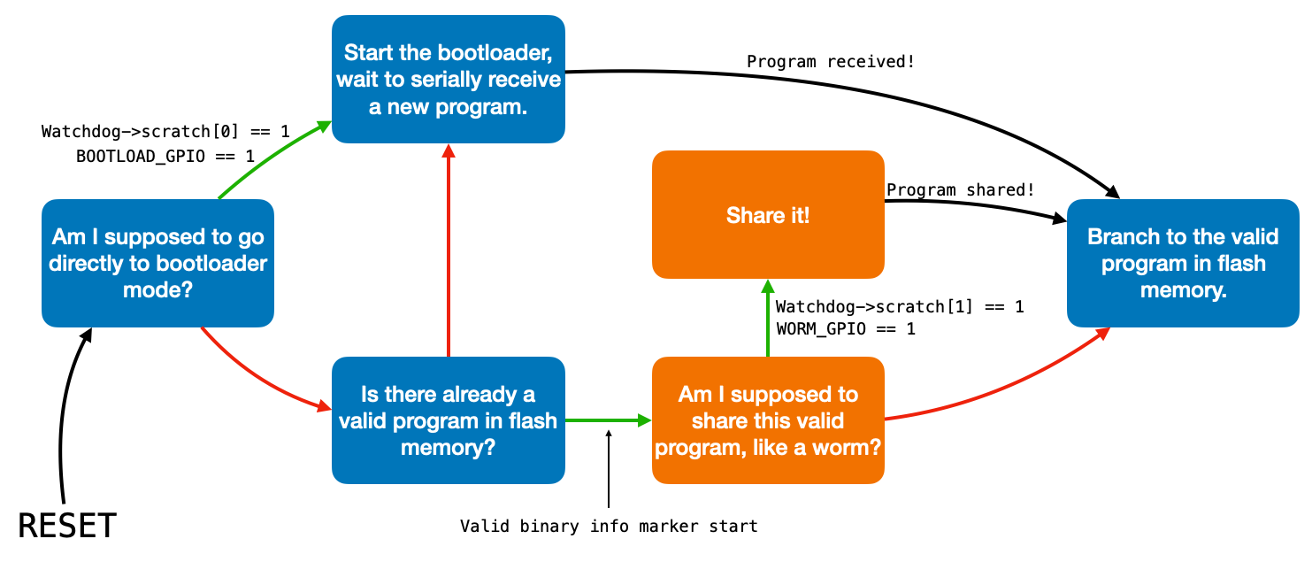
In the diagram above green arrows indicate affirmative answers to questions, red arrows indicate negative answers, and black arrows indicate unconditional transitions.
The serial bootloader webpage describes each part of this state machine except for the boxes drawn in orange. These are the augmentations which are required to turn the bootloader into a worm, and the ones that the rest of this webpage will discuss.
Telling the bootloader to share its program
In order to determine whether it should share its valid program, the bootloader must check something to see if the user (or a program which forced a soft reset) is commanding the RP2040 to enter worm mode to share its program. In fact, the bootloader allows for the user to force the system into worm mode by holding down a button attached to a GPIO port, and it also allows for a program to force the system into bootloader mode using a watchdog peripheral scratch register.
The watchdog peripheral can perform a soft reset of the RP2040, and it offers eight scratch registers which retain their value through a soft reset (but, importantly, not through a hard reset). These scratch registers are described on page 548 of the RP2040 datasheet. If a program wants to force the system back into bootloader mode, it writes a 1 to watchdog scratch register 1 and then forces a soft reset. After the soft reset, the bootloader will check both a GPIO and scratch register 1 for an answer to question 1 above.
How the bootloader shares its program
In the event that the bootloader is sent into worm mode by a GPIO port or by a watchdog scratch register, it calls the function shareApplication(). This function is linked here, and discussed by section below.
Initializing UART
The first thing that the shareApplication() function does is initialize the UART channel. It is initialized for 1 stop bit, 8 data bits (since we'll be sending characters), default parity, and a baud rate of 4800. The baud rate is 4800 for compatibility with the wireless infrared UART interface.
// Setup UART
// Initialize the UART channel
uart_init(UART_ID, BAUD_RATE) ;
// Set our data format
uart_set_format(UART_ID, DATA_BITS, STOP_BITS, PARITY);
// Turn off FIFO's - we want to do this character by character
uart_set_fifo_enabled(UART_ID, false);
// Set the TX and RX pins by using the function select on the GPIO
gpio_set_function(UART_TX_PIN, GPIO_FUNC_UART);
gpio_set_function(UART_RX_PIN, GPIO_FUNC_UART);
gpio_pull_up(UART_RX_PIN) ;
Initializing PWM
The shareApplication() function then initializes and starts a PWM channel to run with a 50% duty cycle at 56 kHz. This drives the IR LED which the UART TX line modulates on and off, as described on the wireless infrared via UART page.
// Initialize PWM
// Tell GPIO 0 and 1 they are allocated to the PWM
gpio_set_function(PWM_PIN, GPIO_FUNC_PWM);
// Find out which PWM slice is connected to GPIO 0 (it's slice 0)
uint slice_num = pwm_gpio_to_slice_num(PWM_PIN);
// Set period of 4 cycles (0 to 3 inclusive)
pwm_set_wrap(slice_num, 2232);
// Set initial B output high for three cycles before dropping
pwm_set_chan_level(slice_num, PWM_CHAN_B, 1116);
// Set the PWM running
pwm_set_enabled(slice_num, true);
Initialize the LED
Because it's useful to see the LED flash as the handshakes occur.
// Initialize the LED pin
gpio_init(LED_PIN);
// Configure the LED pin as an output
gpio_set_dir(LED_PIN, GPIO_OUT);
Initialize the flash pointer
We are going to read the contents of flash memory and sent those contents, over the wireless serial link, to the receiving RP2040. We'll start reading the contents of flash memory at the very beginning of the application code.
// The pointer to flash memory
uint8_t* flash_pointer = application_start ;
Per the modified linker script discussed on the serial bootloader webpage, or at an address of 0x10003000. application_start, a global, is initialized as shown below.
// Application program offset in flash (12*1024)
// This should agree with the linker script for the
// application program.
#define PROGRAM_OFFSET 32768

// Application information for programming another Pico
uint8_t *application_start = (uint8_t *)(XIP_BASE + PROGRAM_OFFSET) ;
Claim and configure a DMA channel
The worm sends data to the receiving RP2040 in accordance with the Intel hexadecimal object file format. This file format is discussed at length on the serial bootloader webpage but, in short, each line includes an address (which will come from the flash_pointer), a length (all will be 16 bytes long, arbitrarily chosen), a record type, the data itself, and a checksum. The checksum is the 2's complement of the LSB of the sum of all bytes in the packet which precede the checksum. The DMA sniffer, described on page 97 of the RP2040 datasheet provides an easy mechanism for computing this checksum. The code below acquires an unused DMA channel, configures it for 8-bit (1-byte) transfers, and configures the associated DMA sniffer. The DMA channel will simply move the packet to a dummy array, computing the checksum as it does so.
// Claim and configure a DMA channel
dma_chan_1 = dma_claim_unused_channel(true) ;

// Configure the first channel (performs checksum)
dma_channel_config c1 = dma_channel_get_default_config(dma_chan_1);
channel_config_set_transfer_data_size(&c1, DMA_SIZE_8);
channel_config_set_read_increment(&c1, true);
channel_config_set_write_increment(&c1, true);
dma_channel_configure(
    dma_chan_1,                     // Channel to be configured
    &c1,                            // Config. we just created
    data_binary_dummy_dest,         // write address
    data_binary,                    // The initial read address
    20,                             // Number of transfers
    false                           // Don't start immediately.
);

// Configure the sniffer!
dma_sniffer_enable(dma_chan_1, 0x0F, true);
hw_set_bits(&dma_hw->sniff_data, 0x0);
Send a few dummy messages
Before sending any valid packets, the worm sends some packets with incorrect checksums. It sends ten of these, separated by about half a second. In the event that the application code which is running on the receiving device can receive UART messages, these dummy messages can be used to tell the other device to force itself into bootloader mode. Once in bootloader mode, any message which fails a checksum is simply ignored.
// Get the other device into bootloader mode
for (int i=0; i<10; i++) {
    for (int k=0; k<17; k++) {
        uart_putc(UART_ID, to_boot[k]) ;
        sleep_ms(UART_SMALL_DELAY) ;
    }
    sleep_ms(UART_DELAY) ;
}
The to_boot array that is being sent is a statically-stored array which encodes an extended linear address message with an incorrect checksum. This is stored globally, and copied below.
unsigned char to_boot[17]       = {':','0','2','0',
                                   '0','0','0','0',
                                   '4','1','0','0',
                                   '0','E','B','\n', '\r'} ;
Clear the UART receive buffer
The FIFO is disabled for the UART, so reading a single character will clear the receive buffer. The receiving device will respond to every packet that it receives with a single character. Reading a character clears the receive buffer for subsequent transactions.
// The FIFO is disabled. One read will clear the rx register
uart_getc(UART_ID) ;
Send extended linear address message
As described on the serial bootloader page, the bootloader state machine responds to a message with the extended linear address record type by preparing to receive a new program. It resets its own programming pointer, clears the first sector of memory, and clears the page buffer in preparation for subsequent data packets to arrive. We send one of these messages to get the receiving device ready to receive the program. Note that we keep sending the message for as long as the receiving device responds to those messages with the character A. This is the receiving device telling us "please send that again." As soon as it's understood the message (i.e., the checksum passed), it will respond with the character B.
// Send the hexline which indicates start of file
do {
    for (int k=0; k<17; k++) {
        uart_putc(UART_ID, start_of_file[k]) ;
    }
}
while (uart_getc(UART_ID)=='A') ;
Send the program
The worm then sends its own application code, 16 bytes at a time. It does so by populating an array called data_binary according to the Intel hexadecimal object file format. The first byte in the array represents the length of the data payload (0x10, or 16 bytes). The second byte represents the most-significant 8 bits of the least-significant 16-bits of the base address for the data payload (the most significant 16 are in the extended linear address packet, per the Intel standard). The next byte is the least-significant 8 bits of the least-significant 16 bits of the address. The next byte is the record type (0x00, which represents "data"). And then we populate the next 16 bytes with the data at the address pointed to by flash_pointer, incrementing flash_pointer each time.
The code then clears the DMA sniffer register, resets the DMA read and write address, starts the DMA channel and waits for it to finish. The DMA sniffer computes a checksum on the data in-flight, and then the last byte of the data binary is populated with the 2's complement of the least-significant byte of this checksum.
All of the binary data in the data_binary array then gets converted to ASCII characters by means of a lookup table, and the resulting array of ASCII hex values gets stored in the character array data. The program reads the most recent character from the receiving device, clearing the receive buffer. It then sends the data array to the receiving device over the UART channel until it receives confirmation that the packet was received without error.
The code continues doing this until it reaches a hard-coded end address, though this hard-coded end address could be replaced with the end of binary address as indicated in the binary info header.
// Send all the data hexlines
    do {

        // Populate the first few bytes of the data binary
        data_binary[0] = 0x10 ;
        data_binary[1] = (unsigned char)((((uint32_t)(flash_pointer)) >> 8) & 0xFF) ;
        data_binary[2] = (unsigned char)(((uint32_t)(flash_pointer)) & 0xFF) ;
        data_binary[3] = 0x00 ;

        // Populate the data into the hexline
        for (int i=4; i<20; i++) {
            data_binary[i] = *flash_pointer++ ;
        }

        // Reset the sniff register to zero
        dma_sniffer_set_data_accumulator(0x00000000) ;

        // Use DMA to compute a checksum
        dma_channel_set_read_addr(dma_chan_1, data_binary, false) ;
        dma_channel_set_write_addr(dma_chan_1, data_binary_dummy_dest, true) ;
        dma_channel_wait_for_finish_blocking(dma_chan_1) ;

        // Populate the checksum into the data binary
        data_binary[20] = (unsigned char)((~(dma_hw->sniff_data) + 0x1) & 0x000000FF) ;

        // Convert the data binary to hex characters
        for (int i=0; i<21; i++) {
            data[(i<<1)+1] = numToHex((data_binary[i]>>4) & 0xF) ;
            data[(i<<1)+2] = numToHex(data_binary[i] & 0xF) ;
        }

        // Make sure the buffer is clear
        uart_getc(UART_ID) ;

        // Send to the receiving device. Keep sending for as long
        // as the response is A
        do {
            for (int i=0; i<45; i++) {
                uart_putc(UART_ID, data[i]) ;
            }
        } while (uart_getc(UART_ID)=='A') ;

        // Blink the LED
        gpio_put(LED_PIN, !gpio_get(LED_PIN)) ;


    } while (data_binary[1]<0xA9) ;
Send the end of file packet
Send a packet with the "end of file" record type, which will cause the receiving device's bootloader to branch into the newly received program.
// Get the other device into application mode
do {
    for (int i=0; i<45; i++) {
        uart_putc(UART_ID, end_of_file[i]) ;
    }
} while (uart_getc(UART_ID)=='A') ;
Clean up
De-init all peripherals, clear all interrupts, free DMA channels, etc. Tidy up before we leave the bootloader.
// Clean up
// Turn off interrupts (NVIC ICER, NVIC ICPR)
hw_set_bits((io_rw_32 *)0xe000e180, 0xFFFFFFFF);
hw_set_bits((io_rw_32 *)0xe000e280, 0xFFFFFFFF);

// Free-up DMA
dma_channel_cleanup(dma_chan_1) ;
dma_channel_unclaim(dma_chan_1) ;

// Disable sniffer
dma_sniffer_disable() ;

// Release UART and GPIO
uart_deinit(UART_ID) ;
gpio_deinit(LED_PIN) ;
gpio_deinit(BOOTLOAD_PIN) ;

// Stop the PWM running
pwm_set_enabled(slice_num, false);
gpio_deinit(PWM_PIN) ;
Branch to our program in flash memory
Call the handleBranch() routine, described in the serial bootloader writeup, which sets the main stack pointer and branches to the application code in flash memory.