PID control of a 1D helicopter
V. Hunter Adams (vha3@cornell.edu)
Note: This is an implementation of an existing PIC32 lab for ECE 4760 created by Bruce Land. The RP2040 stuff is new, but the assembly and circuit design all come from Bruce.
Objective
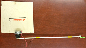
This page describes the construction and control of a one-degree-of-freedom helicopter. A small drone motor is rigidly attached to the end of a lever-arm, the other end of which is attached to a low-torque potentiometer. The drone motor can lift the arm, and the angle of the arm is measured by the potentiometer. The user can select a target arm-angle and a PID controller will drive the arm to that angle.
The target and measured angle are displayed on the VGA screen and the user specifies new target angles through a serial interface to the RP2040. A demo is shown below.
Project Zip
Please email me for code. This project is closely related to an existing PIC32 project that I teach in a course, so I am not posting all of the code here.
Code organization
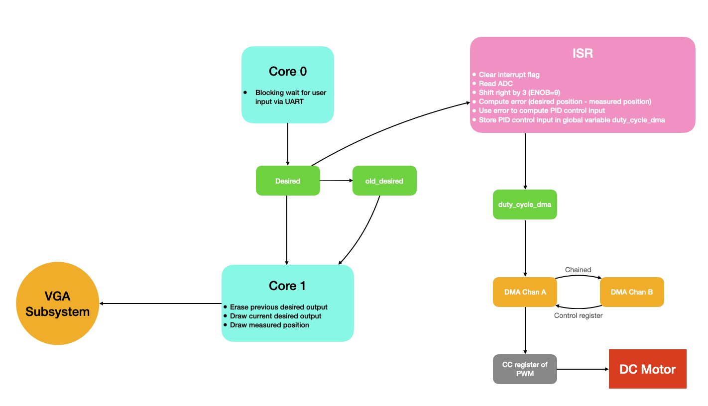
This project uses both cores of the RP2040, an interrupt service routine, PWM peripheral hardware, UART peripheral hardware, the ADC, and two DMA channels. It also uses the VGA subsystem, which is described at length on this page.
Core 0 sits and blocks, waiting for serial input from the user specifying a new target angle for the 1 DoF helicopter. Meanwhile, Core 1 constantly updates the VGA screen. It draws a horizontal line at the user-specified target angle along with the current measured angle for comparison. VGA updates only take place at 40 Hz so that the screen is not re-drawn too quickly. In other words, if the VGA is acting like an oscilloscope, I've chosen an update rate such that the time/division is long enough to be useful.
Much of the logic takes place in the interrupt service routine, which is running at 1kHz. The ISR clears the interrupt flag, reads the ADC, shifts the ADC measurement right by 3 (according to the datasheet, only the most significant 9 of the 12 ADC bits are effective), computes the difference between the desired and measured helicopter angles, uses that difference to compute a PID control input to the DC motor, and stores that control input in a global variable. A DMA channel whisks this control input off to the CC register of the PWM channel to set the duty cycle, and a second DMA channel reconfigures and restarts the first.
Hardware overview
(from the the existing PIC32 lab)
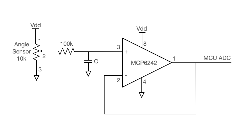
Angle sensor circuit
The angle sensor is a 10k potentiometer. The potentiometer output passes through an anti-aliasing low-pass filter (with R and C chosen as appropriate for a 1KHz sample rate) and into the MCP6242 opamp. This opamp is configured in as a unity-gain buffer, the output from which goes into the RP2040 ADC.
Motor circuit
The motor circuit must protect the microcontroller from the large $L \frac{dI}{dt}$ voltage spikes that come off of a PWM-driven DC motor. The 4N35 optoisolator completely isolates the MCU from the motor. The 1N4001 snubber diode provides a path to ground for reverse-polarity spikes coming off the motor, and the capacitor in parallel with the 1N4001 provides a path to ground for higher frequency noise. Some of the components in this circuit require some experimentation/trial and error. The resistor attached to the base of the 4N35 should be set for best falltime, probably ~1MOhm. The capacitor in parallel with the motor should be ceramic (electrolytics are too slow) and should start with a value ~0.1uF. If there is too much spike noise on the analog input, this value can be increased.
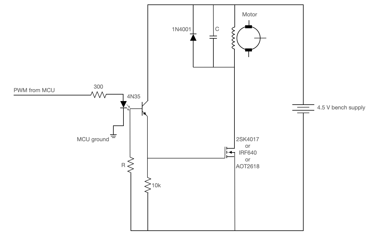
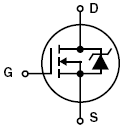
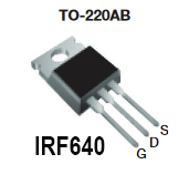
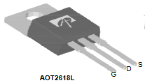
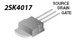
The pinouts for the 4N35 optoisolator and power MOSFET's are shown below. Note that it is the bandwidth of the 4N35 that constrains the PWM frequency. The bandwidth for this device is low, so we'll use a PWM frequency of about 1kHz.
 |
 |
 |
 |
 |
Mechanical construction
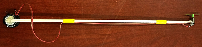
- Hot glue a motor to one end of the wooden beam. Note that the motor shaft should be at right angles to the rotation shaft of the knob.
- Roughen the knob surface using sandpaper. Be sure to remove the plastic film.
- Hot glue the other end of the wooden beam to the knob surface.
- Solder a pair of wires (from ribbon cable) to the motor and tape them to the beam. Note: Use only stranded wire peeled off from ribbon cable.
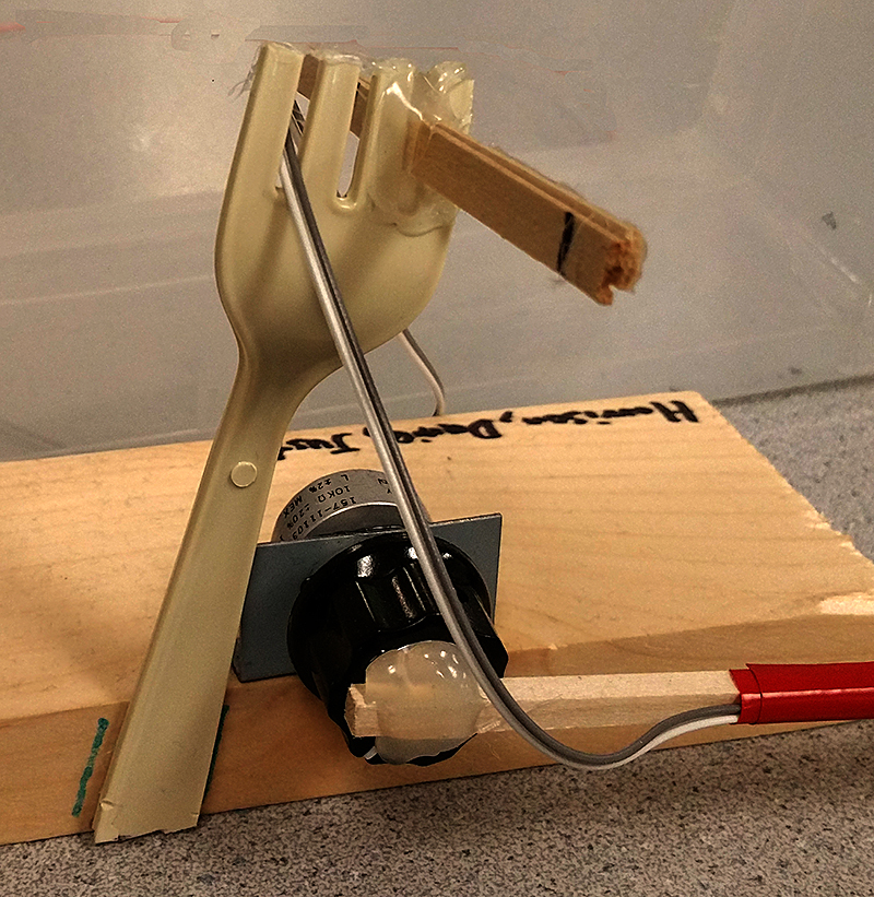
- Screw the potentiometer bracket to a chunk of wood big enough that you can use a book to weigh it down. Use #4 screws, as shown in the image below. Hot gluing the bracket to the wood will cost you 10 points in the lab.
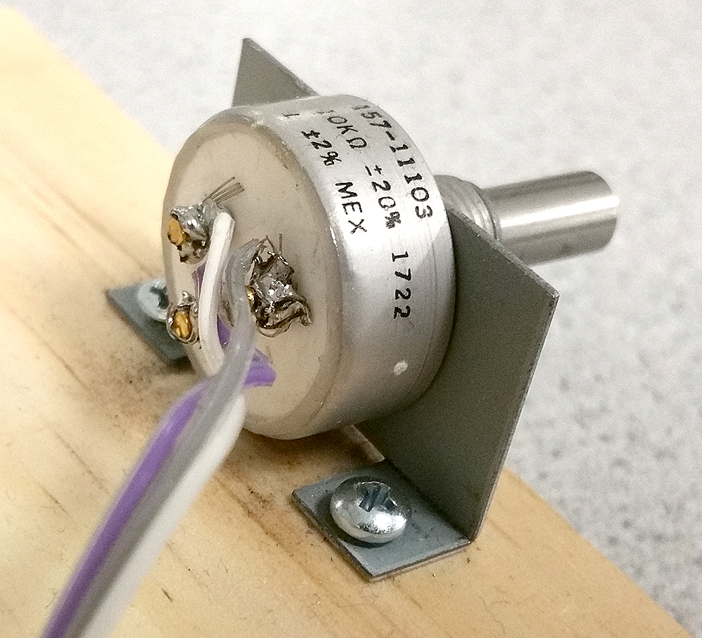
- The potentiometer mounting hold on the bracket is slightly too small for the potentiometer sleeve. You will need to use the rat-tail (round) file to enlarge the hole.
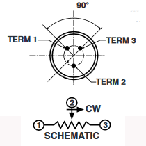
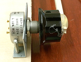
- When attaching the potentiometer to the mounting bracket, be sure that the locating pin (see data sheet) is in the appropriate sheet metal slot. The shaft on these potentiometers is freely rotating. Therefore, when attaching the beam to the potentiometer shaft you need to check the whole range of shaft motion for continuous resistance. I suggest adjusting the pot to 1/2 full resistance, then attach the knob to the potentiometer shaft with the wooden beam held in the horizontal position.
- Be sure to use pliers to tighten the potentiometer on the bracket.
- Use a 1/16 hex wrench to tighten the knob onto the shaft. Hot gluing the knob to the potentiometer will cost you 20 points on the lab.
- Solder three wires (from ribbon cable) to the potentiometer.
- Figure out how to put a rotation-stop on the beam so that it cannot go past vertical. A piece of wire works, or a coffee stir-stick, or a drinking straw, or a fork from Mattins.
VGA connections and circuit
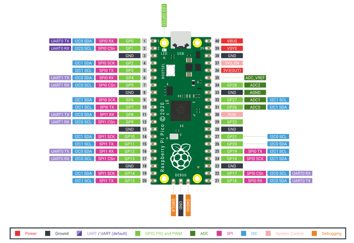
Please see the VGA page. I am using the GPIO pins listed below. As explained on the VGA page, the HSYNC and VSYNC lines are connected directly to the VGA connector, and the color lines are connected in series with a 330 ohm resistor.
HSYNC: GPIO 16VSYNC: GPIO 17RED: GPIO 18GREEN: GPIO 19BLUE: GPIO 20
Setting up the ADC
Because we will sample the ADC in software (rather than using DMA), the setup is way simpler than it was for the audio FFT. We simply call adc_init() which resets the ADC, turns it back on, and prepares the internal 48MHz clock. We then call adc_select_input() which takes, as an argument, the ADC MUX number. For GPIO 26, this is 0.
// Setup the ADC on GPIO 26 (MUX0)
adc_init() ;
adc_select_input(0) ;
Setting up PWM
We desire a 1kHz PWM signal that throws an interrupt after each period. In order to do this, we first select the pin that we want to use as our PWM output (5, in this case) and specify the PWM slice to which this GPIO belongs. We then setup the interrupt. We clear interrupts associated with the relevant PWM slice, enable interrupts for that slice, specify the interrupt handler that will fire each time the PWM wraps, and enable the interrupt.
Next, we clock divide the PWM from 125MHz to 25MHz, and we set the wrap value to 25000. This will cause the signal to wrap at precisely 1kHz. Finally, we initialize the duty cycle for the PWM to an arbitrary value, since the controller running in the ISR will be manipulating the duty cycle.
#define WRAPVAL 25000
#define CLKDIV 5.0f

// Tell GPIO 5 it is allocated to the PWM
gpio_set_function(5, GPIO_FUNC_PWM);

// Find out which PWM slice is connected to GPIO 5 (it's slice 2)
uint slice_num = pwm_gpio_to_slice_num(5);

// Mask our slice's IRQ output into the PWM block's single interrupt line,
// and register our interrupt handler
pwm_clear_irq(slice_num);
pwm_set_irq_enabled(slice_num, true);
irq_set_exclusive_handler(PWM_IRQ_WRAP, on_pwm_wrap);
irq_set_enabled(PWM_IRQ_WRAP, true);

// This section configures the period of the PWM signals
pwm_set_wrap(slice_num, WRAPVAL) ;
pwm_set_clkdiv(slice_num, CLKDIV) ;

// This sets duty cycle, and will ultimately be
// manipulated via a DMA channel
pwm_set_chan_level(slice_num, PWM_CHAN_B, 3125);
Setting up DMA to PWM
A DMA channel whisks the PWM duty cycle off to the PWM peripheral. In order to accomplish this, we setup two DMA channels. One sends the duty cycle data from a global variable (set in the ISR) to the PWM's CC register, and the other reconfigures and restarts the first. We'll refer to these as the data and control channels, respectively.
The data channel is configured for 32-bit transfers, no read incrementing, no write incrementing, and is paced by PWM overflows (so a transfer occurs every PWM period). Note that the CC register is double-buffered, so there is no artifact in the PWM signal from dynamically changing the duty cycle. The duty cycle will always change at the beginning of a new period.
The data channel is chained to the control channel. Is transfers from a global variable called duty_cycle_dma to the cc register of the particular PWM slice that we are using. It only does a single transfer before stopping, waiting to be reset by the control channel.
The control channel writes a 1 to the transfer count trigger register of the data channel, which restarts it. The data channel will not start a new transfer until the next PWM wrap event. Note too that the duty cycle for a PWM channel is 16 bits, but the cc register is 32 bits. The top 16 bits are for PWM channel B, and the bottom are for channel A for a particular PWM slice.
// Use channels 2 and 3, in case we want to add VGA capability (which uses 0, 1)
int pwm_chan = 2 ;
int control_chan = 3 ;

// Create two DMA configuration objects
dma_channel_config c2 = dma_channel_get_default_config(pwm_chan) ;
dma_channel_config c3 = dma_channel_get_default_config(control_chan) ;

// PWM TXFER CHANNEL
channel_config_set_transfer_data_size(&c2, DMA_SIZE_32);        // 32-bit txfers
channel_config_set_read_increment(&c2, false);                  // no read incrementing
channel_config_set_write_increment(&c2, false);                 // no write incrementing
channel_config_set_dreq(&c2, DREQ_PWM_WRAP2);                   // paced by PWM wrapping
channel_config_set_chain_to(&c2, control_chan) ;                // chained to control channel

dma_channel_configure(
    pwm_chan,                       // Channel to be configured
    &c2,                            // The configuration object (pointer)
    &pwm_hw->slice[slice_num].cc,   // destination (counter compare register)
    &duty_cycle_dma,                // source (global variable)
    1,                              // transfer count
    false                           // Don't start immediately
);

// PWM CONTROL CHANNEL
channel_config_set_transfer_data_size(&c3, DMA_SIZE_32);     // 32-bit txfers
channel_config_set_read_increment(&c3, false);               // no read incrementing
channel_config_set_write_increment(&c3, false);              // no write incrementing

dma_channel_configure(
    control_chan,                                       // Channel to be configured
    &c3,                                                // The configuration we just created
    &dma_hw->ch[pwm_chan].al1_transfer_count_trig,      // Write address (txfer count trigger)
    &transfer_count,                                    // Read address (POINTER TO AN ADDRESS)
    1,                                                  // Number of transfers, in this case each is 4 byte
    false                                               // Don't start immediately.
);
The ISR
All of the high-speed measurement and control logic lives in the ISR. Note that we shift out the least significant 3 bits of the 12-bit ADC measurement. Per the datasheet, there are only 9 effective bits, the bottom 3 being largely noise. For that reason, we simply shift them to oblivion.
The ISR clears the interrupt flag, gathers/shifts a measurement, computes the error, uses the error to compute a PID control input, and sets a flag variable to signal to the VGA driver on core 1 that it has a new measurement to write to the screen.
The code is not listed here because it's very similar to that for a lab assignment in my class.
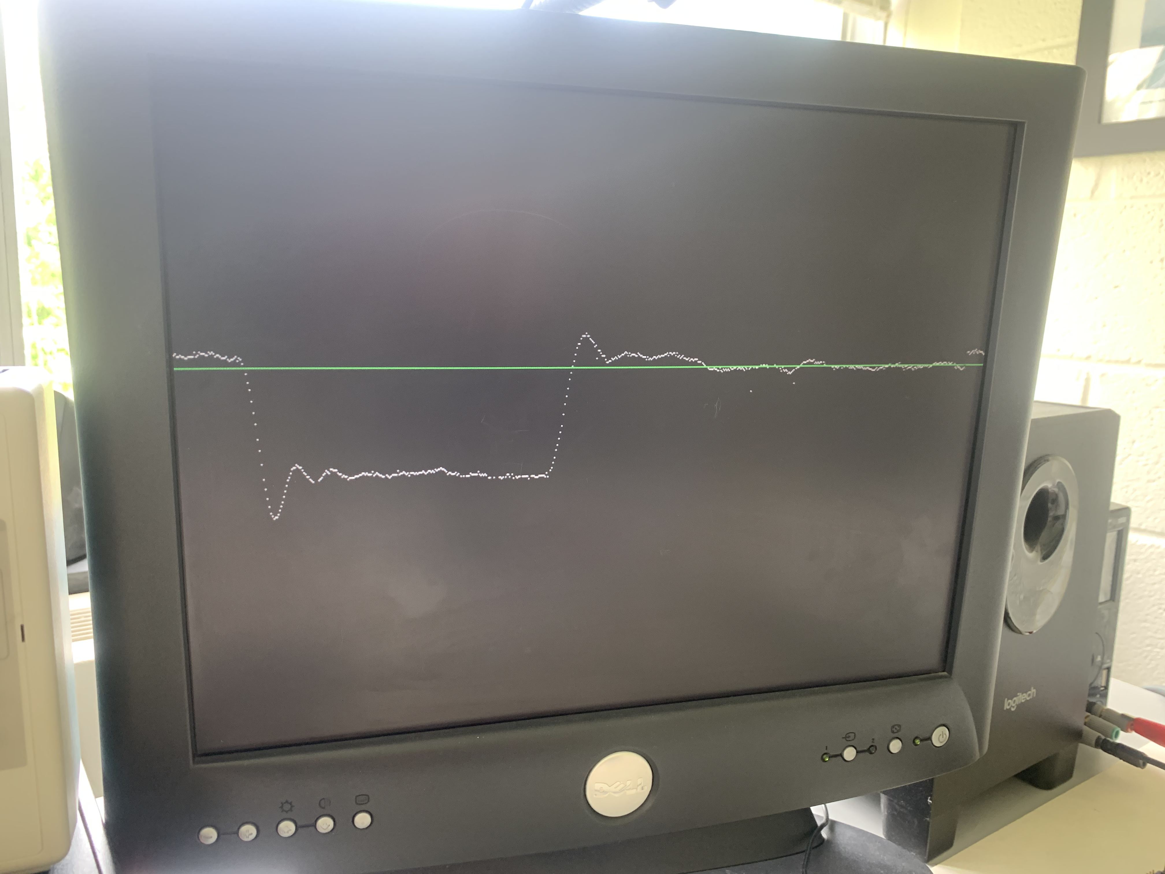
VGA display
The VGA screen shows the current target angle as a horizontal green line, and the current measured angle with white dots. In the image below, you can see that the arm started at a relatively high target angle, moved to alower target, and then moved back up to a higher target. You can see the overshoot/ringing from the underdamped PID controller.