Complementary filters
V. Hunter Adams
A complementary filter is a quick and effective method for blending measurements from an accelerometer and a gyroscope to generate an estimate for orientation. This webpage briefly explains why such a filter is necessary, how it works, and then offers some alternative filters that you might consider. As a case-study problem, we will consider estimating the tilt angle of an inverted pendulum.
System under consideration
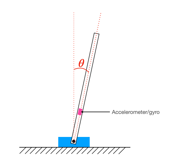
As a case study problem, let us consider an inverted pendulum (just like in the reaction wheel laboratory assignment). In order to control this pendulum, we must measure the angle $\theta$ shown below. In order to determine this angle, we will use an accelerometer and a gyroscope mounted on the pendulum arm.
Demonstration video
Accelerometer vs. Gyroscope
With an accelerometer and a gyroscope, we have two different methods for estimating the tilt angle of the inverted pendulum. Unfortunately, there's a problem with each method!
Computing accelerometer angle
The accelerometer measures the direction of gravity, which (in the laboratory) is always toward the center of the Earth. If the accelerometer is oriented on the arm as shown in the image below, then the tilt angle is given by:
\begin{align} \theta &= \arctan{\frac{a_x}{a_y}} \end{align}If we assume that the tilt angle is small (which we can't for the helicopter lab, but we can for the reaction wheel lab), then we can use a small angle approximation! Thus the tilt angle is given by:
\begin{align} \theta &\approx \frac{a_x}{a_y} \end{align}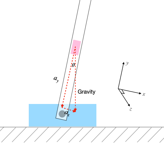
What's bad about the accelerometer?
The problem with the accelerometer is that it is noisy. It becomes especially noisy in the presence of any sort of mechanical noise (e.g. a DC motor attached to the pendulum). In the demonstration video, you can see the accelerometer angle plotted on the VGA display as I move the inverted pendulum back and forth. When I turn on a DC motor attached to the pendulum arm, the noise increases. This is much too noisy to use in a feedback controller.
What's good about the accelerometer?
Because gravity always points in the same direction, the measurement error from the gyroscope remains zero-mean. The accelerometer does not accumulate any measurement bias, like the gyroscope does. The measured acceleration is equal to the true acceleration plus zero-mean Guassian noise, where the variance of that Gaussian noise can be quite large.
Computing gyro angle
The gyroscope directly measures rotation rate. So, if we know the initial angle for our system ($\theta_0$) and our sample rate ($\frac{1}{\Delta t}$), we can use the gyroscope to integrate that angle for all time.
\begin{align} \theta = \theta_0 + g_z \Delta t \end{align}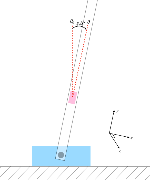
What's bad about the gyro?
By integrating the gyro measurements to maintain an estimate for angle, we are doing dead reckoning. This works great over short periods of time, but eventually leads to a large bias in our angle estimate. You can see this in the demonstration video. Even as I hold the pendulum at a constant angle, the gyroscope error continues to accumulate a bias. This bias is driven by a random process, so it may wander in any direction.
What's good about the gyro?
Over short periods of time, the amount of noise in the gyroscope measurements is much lower than that from the accelerometer. You can see this in the demonstration video. As I move the pendulum back and forth, note that there is very little noise on the (red) gyroscope measurements, and a lot of noise on the (white) accelerometer measurements.
Complementary filter
We desire the short-term accuracy of the gyro angle estimates, and the long-term stability of the accelerometer angle estimates. A complementary filter achieves this! A complementary filter low-passes the accelerometer measurements and high-passes the gyroscope measurements. This gives us the benefit of the gyro over short time periods, and the stability of the accelerometer over long time periods.
The algorithm is summarized as follows:
- Gather a set of accelerometer and gyro measurements
- Compute the accelerometer angle
- Compute the change in angle that the gyro measures, by multiplying the raw measurement by the timestep (0.001 seconds in the example code below)
- Compute the new complementary angle estimate by performing a weighted average of the accelerometer angle and the sum of the previous complementary angle estimate and the change in angle measured by the gyro.
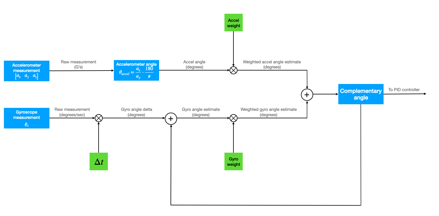
Choosing these weights is a part of your tuning process. The greater the weight on the accelerometer, the less bias and more noise you see in your angle estimates. Start with an accelerometer weight of ~0.01 and a gyro weight of ~0.99. You can initialize the complementary angle using the accelerometer angle. The snippet below encodes the algorithm above.
// Gather measurements
mpu6050_read_raw(acceleration, gyro);

// Accelerometer angle (degrees - 15.16 fixed point)
// Only ONE of the two lines below will be used, depending whether or not a small angle approximation is appropriate

// SMALL ANGLE APPROXIMATION
accel_angle = multfix15(divfix(acceleration[0], acceleration[1]), oneeightyoverpi) ;
// NO SMALL ANGLE APPROXIMATION
accel_angle = multfix15(float2fix15(atan2(-filtered_ax, filtered_ay) + PI), oneeightyoverpi);

// Gyro angle delta (measurement times timestep) (15.16 fixed point)
gyro_angle_delta = multfix15(gyro[2], zeropt001) ;

// Complementary angle (degrees - 15.16 fixed point)
complementary_angle = multfix15(complementary_angle - gyro_angle_delta, zeropt999) + multfix15(accel_angle, zeropt001);
Quick note!
If you are not using a small angle approximation to compute the accelerometer angle (like in the helicopter lab), you may need to low-pass the raw accelerometer measurements before computing the accelerometer angle. Why? Think about how white noise propatates through the atan2 function.
What are the alternatives?
There are other methods for estimating attitude and other system states that are both more accurate and more complicated. See the links below.