PID control of a 1D helicopter
V. Hunter Adams
Note: This is a minor rewrite of an existing PIC32 lab for ECE 4760 created by Bruce Land.
Introduction
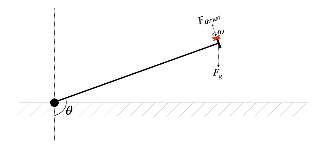
In this lab, you will construct and control of a one-degree-of-freedom helicopter. A small ducted is rigidly attached to the end of a lever-arm, the other end of which is attached to a hinge. The drone motor can lift the arm, and the angle of the arm is estimated via a complementary filter of accelerometer and gyro measurements from an onboard IMU. The user can select a target arm-angle and a PID controller will drive the arm to that angle.
The target and measured angle are displayed on the oscilloscope or the VGA screen and the user specifies new target angles through a serial interface to the RP2350.
Key concepts: I2C communication, PID control, electrical isolation of DC motors, optical isolators, PWM, complementary filters, gyroscopes, accelerometers, gyro bias, mechanical assembly, navigating sensor datasheets, UART, VGA, digital low-pass filtering
Demonstration
A demo is shown below.
Reading
Experience shows that students prefer these webpages short. For that reason, please find the reading and background materials on the webpages linked below. Please note that the information in these readings will be critical for completing the lab.
Theoretical background
- Complementary filters: A method for estimating angle from gyroscope and accelerometer measurements. This is a great algorithm for your toolbox. Quick, easy, and effective.
- Phenomenological introduction to PID controllers: This document focuses on building a phenomenological understanding of PID controllers through demos. The hope is that this document will help you debug your system based on the behavior that you observe in lab, and the one below will help you understand that behavior.
- Analytical introduction to PID controllers: This document focuses on building an analytical understanding of these controllers. The hope is that the phenomenological document will help you debug your system based on the behavior that you observe in lab, and this one will help you understand that behavior.
Engineering background
- Mechanical contruction of the lever arm: This webpage provides instructions for the mechanical construction of the lever arm.
- Motor circuit and PWM: This webpage describes the circuit that you will construct to safely drive the DC motor, and how to generate PWM.
- Data display: This webpage describes the data that you must visualize in realtime, and some strategies for visualizing that data.
- I2C communication: You will communicate with the IMU via an I2C channel. An understanding of the I2C protocol will help you debug that connection.
- RP2350 datasheet: See chapters on PWM and I2C.
- RP2350 C SDK: See chapters on PWM and I2C.
Optional book-club reading
- Leonardo da Vinci by Walter Isaacson: Chapters 23-33
Program organization
You may organize your program however you like. Here is a suggestion:
- Protothreads maintains the ISR-driven, millisecond-scale timing as part of the supplied system. Use this for all low-precision timing (can have several milliseconds jitter).
- PID ISR uses a timer or PWM interrupt to ensure an exact 1kHz control rate.
- Clears the interrupt flag
- Reads the IMU to get raw accelerometer/gyro measurements
- (Possibly, low-passes the accelerometer measurements)
- Estimates angle by menas of a complementary filter of accel/gyro measurements
- Runs the PID control loop at 1000/sec using the angle estimates from the complementary filter
- Sets a hardware PWM signal using output-compare unit to control the motor using the command:
pwm_set_chan_level(slice_num, PWM_CHAN_X[A or B], pwm_on_time);. - (possibly) communicates measured angle and low-passed control input to DAC
- Main sets up peripherals and protothreads then just schedules tasks, round-robin
- Thread 1
- Takes user input from the serial interface to setup PID parameters and the desired angle.
- Thread 2
- (possibly) diplays measured angle and low-passed control input on VGA display
Weekly checkpoints and lab report
Note that these checkpoints are cumulative. In week 2, for example, you must have also completed all of the requirements from week 1.
Week one checkpoint
By the end of the lab session in week one of the lab you must have:
- The mechanical assembly finished and be able to control motor speed open loop, from the PWM output. Here is some demo code to get you started. See the motor circuit page.
- You will build your motor control circuit on a printed circuit board, not on the breadboard! See the motor circuit page.
- Finishing a checkpoint does NOT mean you can leave lab early!
Week two checkpoint
By the end of the lab session in week two of the lab you must have:
- Display of the actual beam angle and the low-passed motor command signal using the VGA display. This is critical for debugging. Here is some demo code for getting started.
- Full closed-loop control of the motor (just proportional control is fine).
- Serial command interface to set PID parameters.
- Finishing a checkpoint does NOT mean you can leave lab early!
Week three assignment
- Measure the angle of the beam supporting the lift-motor, display the beam position either on the oscilloscope or the VGA screen.
- Format the set angle and PID parameters to display appropriate messages on the VGA display or the serial console.
- At any time, take commands from the serial interface to:
- Set the desired beam angle
- Set the PID proportional gain
- Set the PID differential gain
- Set the PID integral gain
- The new values should take effect immediately
- One set of coefficients should produce stable behavior over the range of desired hover angles
- Use a PID control algorithm to control the speed of the motor by producing a PWM drive to the optoisolator. PWM setup example.
- Tune the PID algorithm so that you can change the angle of the beam quickly and accurately without excessive angle oscillations.
- The user should be able to enter a desired hover angle and the motor should quickly change the beam to the new angle. The initial angle of the beam should be around -1.57 radians (hanging straight down).
- Display the motor control value (not the raw PWM signal) on the scope or VGA. Noise control on this signal is essential. If you cannot see the shape of the control signal, you will not get credit for this feature! You may need to combine DSP and analog filtering, depending on exactly how you build the circuit.
- Display the actual beam angle, from the angle sensor, on the VGA. If this signal is noisy, you need to find out why! Poor wire routing, loose connections, and motor noise are all posibilities. A noisy input makes the control PID algorithm very hard to tune.
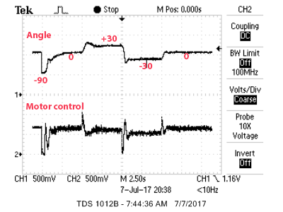
- When a button is pushed (not the reset button), the beam should go through a quick sequence of defined angle changes, using the current set of PID parameters:
- Before time=0, while holding the button, the beam should be hanging vertically down (motor off)
- When the button is released at time=0, target angle should be set to horizontal
- At time=5 seconds, target angle should be set to approximately 30 degrees above horizontal
- At time=10, target angle should be set to approximately 30 degrees below horizontal
- At time=15, target angle should be set to horizontal
You will demo all of the features above to a course staff member. You program should not need to be reset during the demo.
Lab report
Your written lab report should include the sections mentioned on the policy page, and:
- A schematic of the circuit you built
- VGA screen dumps of typical two-trace: (1) motor-control and (2) actual angle. Include the demo sequence of four angles, as shown below
- How you selected the three PID gains.
- What are the maximum/minimum angles that produce stable behavior for your PID gains?
- What are the settling times at different angles?
- A heavily commented listing of your code.
- A prompt log from any AI tool that you used for code generation. The log should include words exchanged, number of code additions/deletions/modifications suggested, and number of code additions/deletions/modification accepted. The AI tool will generate this log for you if prompted to do so.