Synthesizing Birdsong with the RP2350
V. Hunter Adams (vha3@cornell.edu)
Introduction
In this laboratory exercise, you will synthesize one of the most common songs of the northern cardinal, a very pretty (and rather vocal) bird that's common in Ithaca. You can listen to this song in the first ten seconds of the recording linked here. Your goal will be to generate a synthesizer that is accurate enough to trick Cornell Ornithology's Merlin Bird ID App.

Fig. 2 shows the spectrogram for the song that we'll be synthesizing. Cardinals and many other songbirds produce almost pure frequency-modulated tones (i.e., they whistle!). As can be seen in the spectrogram below, the cardinal sweeps through frequencies from ~2kHz to ~7kHz. We'll assume that the dominant tones (the darkest lines on the spectrogram) are significantly louder than all other frequencies (the lighter lines). We'll only synthesize these loudest frequencies. The generated song sounds quite realistic under this assumption, as demonstrated in the embedded video farther down the webpage.
Rather than building a static synth, your user interface will allow for the user to program new sounds into the device! This means that you can try to emulate lots of other birds (or whales? R2D2? crickets?), or use your device as an instrument. We'll reprogram the device via a keypad and a slide potentiometer.
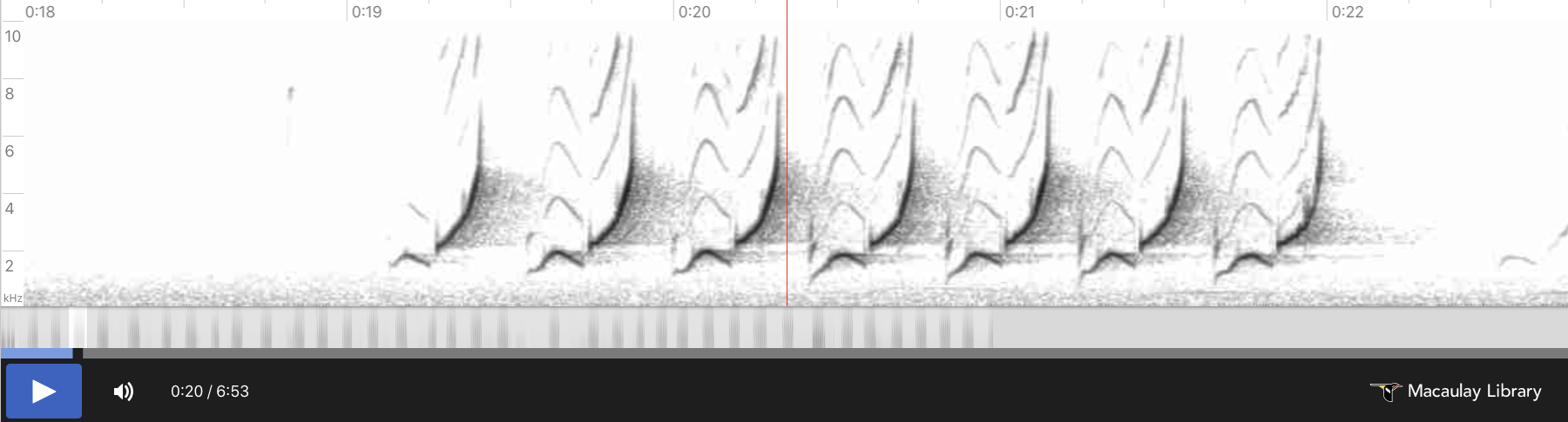
There will be a number of interesting outcomes from this laboratory exercise. You'll gain familiarity with all of the key concepts listed below, but you may also notice that something strange occurs in your own brain! After gaining such an intimate understanding the cardinal's song, you may find that you notice birds singing after completing this lab! It's really nice when an engineering project changes the way that you see and appreciate the world around you, I hope that occurs for some of you.
If you'd like to take things farther, you can also synthesize songs for other, more challenging birds like the Baltimore oriole. (If you're lucky, you can spot these in Ithaca too. They're gorgeous and have a very distinctive song). If you're feeling really ambitious, do additive synthesis to generate a Bobolink (might make a good final project!).
Key concepts: Timers, timer interrupts, Direct Digital Synthesis, SPI communication, GPIO, threading/concurrency, digital-to-analog converters, analog-to-digital converters, potentiometers, fixed-point arithmetic, keypads, debouncing, code characterization
Demonstration
I've embedded a demo below of the system that you will build.
Required reading
Experience shows that students prefer these webpages short. For that reason, please find the reading and background materials on the webpages linked below. Please note that the information in these readings will be critical for completing the lab.
Course information
- Policy page: This page describes the structure and format of the course, course expectations, and grading policies.
- Course demo code: Familiarize yourself with the layout of this repository, and the examples that it contains.
Engineering background
- Building demo code: This webpage describes how to download and build the course demo code.
- C/C++ SDK architecture for RP2040/RP2350: This webpage describes the organization of the C SDK.
- Using the C SDK: This webpage provides a brief practical introduction to the C SDK by means of a simple example.
- Audio examples of incremental complexity: In this lab, as in all labs, you are provided with demo code from which to start your assignment. This repository contains a sequence of example projects which incrementally build to the demo code from which you should start your assignment. The documentation for each of these examples is meant to be read in order.
- Keypad: Your birdsong synthesizer will be cotrolled via a keypad. Please see this page for examples of and information about the keypad that we will be using, and clues about a debouncing state machine.
- SPI Communication: The digital-to-analog converter that we are using is an SPI device. This webpage describes SPI communication. Understanding these concepts will make configuring the SPI channel on the RP2040 much easier.
- RP2350 Datasheet: Sections on GPIO, SPI, Timer, and UART
- C SDK hardware API: Same sections as above
- DAC datasheet: Datasheet for the MCP4822 12-bit DAC that we'll be using in this lab.
- Slide potentiometer datasheet: Datasheet for slide pot.
Mathematical & algorithmic background
- Direct digital synthesis (DDS): This is the algorithm that we will use for sound production. This is a powerful algorithm, a good one to understand deeply.
Related reading
- How and why birds sing: A Cornell Ornithology webpage about birdsong.
- More information about Northern Cardinals: A Cornell Ornithology webpage about cardinals.
- Fast Fourier Transform: How does Merlin generate those spectrograms? It does so by computing FFT's! This webpage describes the Cooley-Tukey FFT.
Optional book-club reading
- Leonardo da Vinci by Walter Isaacson: Chapters 1-11
Weekly Checkpoints
Note that these checkpoints are cumulative. In week 2, for example, you must have also completed all of the requirements from week 1. Look ahead, and design your system with thoughtfulness to the features that you will need to add in the subsequent weeks.
Homework before week 1
- Using this webpage as a guide, download and build the course demo code on your PC
- Read the course policy page. If you have any questions, ask Hunter! This is the implicit contract to which you are agreeing by taking this course, now's the time to seek any clarification you may require.
Week 1
In this example code, direct digital synthesis is used to generate a pure tone. Connect the DAC to the Pico per the
#definestatements at the top of the source code and the DAC datasheet, build the code, and load it onto the Pico. Please note that different manufacturers use different names for SPI signals! Here are the correct connections:3.3V(OUT)-->VDD
GND-->VSS
PIN_CS--> $\overline{\text{CS}}$
PIN_SCK-->SCK
PIN_MOSI-->SDI
LDAC--> $\overline{\text{LDAC}}$Confirm that the waveforms are being generated by the DAC with the oscilloscope, then use a 3.5 mm audio socket so that you can plug in speakers and listen to the tone.
- Modify the code such that the waveform is sent to the other DAC output channel.
- Add the
bootselbutton to your breadboard, as described on this webpage - Add a slide potentiometer to your breadboard, use the ADC demo code to confirm that your connections are correct.
- Integrate the ADC demo code with the DDS tone generating code. The frequency of the tone generator should be set with the slide potentiometer, with a range of 0 to ~10kHz. I recommend augementing the ADC demo with the DDS demo, rather than augmenting the DDS demo with the ADC demo.
Week 2
- Use the keypad webpage to connect the keypad to the Pico. Use the keypad example code to confirm that your connections are correct.
- Integrate the keypad example code with the your potentiometer-controlled tone generator code from last week. Have the program produce a tone when you press/release the 0 key, and stop producing a tone when you press/release the 0 key again. This requires debouncing the keypad.
- Modify the program such that pressing/releasing the asterisk button puts the device into "Record Mode." The user can push/hold any key 1-9, and the frequencies will be recorded while they hold down that button. Releasing the button stops the recording, and pressing/releasing that key again plays back the recording. The user can press/release the asterisk again to re-record a sound to any key 1-9. *Note, you are storing the frequency, not the waveform. You only need to store the frequency at ~100Hz.
- The program should set a GPIO pin when it enters the synthesis ISR, and clear the GPIO pin when it leaves the synthesis ISR. Use the oscilloscope to measure the time that you are spending in the ISR.
- Finishing a checkpoint does NOT mean you can leave lab early!
Week 3 (4760)
Write a C program that meets the following requirements . . .
- The system boots in tone generator mode. It generates a pure tone of a frequency which is adjustable by moving the slide potentiometer.
- Pressing/releasing the 0 key silences the tone generator. Pressing/releasing the 0 key again starts the tone generator.
- Pressing/releasing the * key puts the device into "Record Mode." The user can then press/hold any key 1-9 and the frequency of the tone generator will be recorded for as long as that key is held down. Releasing the key stops the recording.
- Pressing/releasing that same key will play back the sound which was just recorded, but at 8-10x speed. This is to help us record rapidly-modulated birdsongs.
- The user can record different sounds to each key 1-9.
- Pressing/releasing the # key puts the device into "Compose Mode." The user can subsequently push a sequence of keys, and that key sequence will be recorded.
- Pressing/releasing the # key again plays back the sequence that the user recorded.
- The program should set a GPIO pin when it enters the synthesis ISR, and clear the GPIO pin when it leaves the synthesis ISR. Use the oscilloscope to measure the time that you are spending in the ISR.
When you demonstrate the program to Hunter or a TA, you will be asked to play back a sequence of sounds which simulates the birdsong in Fig. 2. If you're able to trick the Merlin App, you will earn a handshake. You will also be asked to play record/playback a random sequence of sounds that Hunter or the TA uses the keypad and slide potentiometer to record. At no time during the demo can you reset or reprogram the Pico. Finishing a checkpoint does NOT mean you can leave lab early!
Week 3 (5730)
In addition to the above requirements for 4760, 5730 students should also . . .
- Add an external switch to the breadboard. When the switch is toggled, the position of the potentiometer is used to set the volume of playback. Toggling the switch back reverts to exactly the behavior described above.
When you demonstrate the program to Hunter or a TA, you will be asked to play back a sequence of sounds which simulates the birdsongs in Fig. 2 and Fig. 3. If you're able to trick the Merlin App, you will earn a handshake. You will also be asked to play back a random sequence of swoops/chirps/silences that Hunter or the TA uses the keypad to generate. At no time during the demo can you reset or reprogram the Pico. Finishing a checkpoint does NOT mean you can leave lab early!
Lab report
Your written lab report should include the sections mentioned in the policy page, and:
- A scope display of a swoop/chirp birdcall showing rise, sustain, fall
- A spectrogram of the sound produced by your MCU. You can generate this anyway you like. You could plug the DAC output into the mic input of your laptop via an aux cable, and then generate a spectrogram in Python. You could alternatively use some software on the lab PC to generate a spectrogram (WaveForms). Or you can use the Merlin app.
- A heavily commented listing of your code
- A prompt log from any AI tool that you used for code generation. The log should include words exchanged, number of code additions/deletions/modifications suggested, and number of code additions/deletions/modification accepted. The AI tool will generate this log for you if prompted to do so.